Universal change-over switch

A transfer switch, a universal technology, applied in the direction of electrical components, contact drive mechanisms, etc., can solve the problems of small electrical clearance and creepage distance, complex design, etc.

Active Publication Date: 2005-11-23
JIANGYIN CHANGJIANG ELECTRIC APPLIANCE
View PDF0 Cites 7 Cited by
  • Summary
  • Abstract
  • Description
  • Claims
  • Application Information

AI Technical Summary

Problems solved by technology

more complex design
[0005] 3. Limited by the size of the switch, the distance between the two pairs...

Method used


Image

  • Universal change-over switch
  • Universal change-over switch
  • Universal change-over switch

Examples


Embodiment Construction

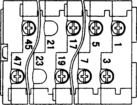
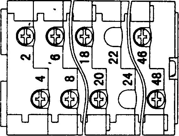
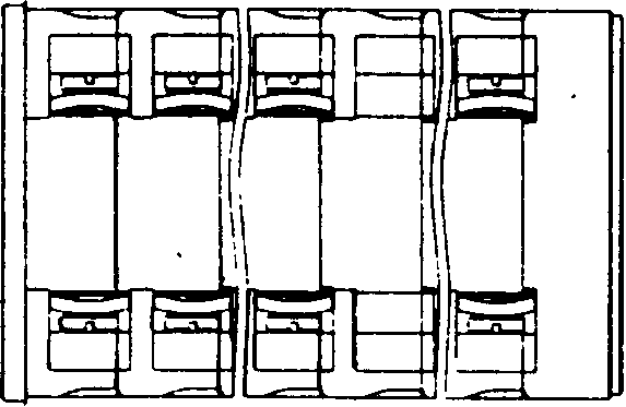
[0014] see Figure 1~3 , The universal transfer switch of the present invention is composed of a multi-layer contact assembly, an operating mechanism (not shown in the figure), and a fixing mechanism (not shown in the figure).

[0015] see Figure 4 , Each layer of the contact assembly of the universal changeover switch is composed of a base 1, electrical contacts 2, 3, a contact bracket 4, a contact spring 5, a terminal screw 6 and a cam 7.

[0016] The base 1 is axially arranged in a stepped shape, and there are two cams 7, which are arranged in parallel axially in the center of the base 1, and there are two contact brackets 4, and the two contact brackets 4 are radially stepped The top and bottom are arranged symmetrically on the inner side of the outer wall of the base 1 , the inner ends of the two contact brackets 4 respectively touch the outer edges of the two cams 7 , and a contact spring 5 is embedded between the outer ends and the inner side of the outer wall of the ...


PUM


Abstract

This invention relates to omnipotence switch, which comprises several layers of touch element with base socket, electrical probe, probe rack, probe spring, interface screw and protruding wheel and is characterized by the following: the base socket is located with step wheels located parallel on the socket center; there are two probe racks and tow probe racks of step symmetrically on outside and inside of the base socket; the two probes racks inner end is connected to the two protruding wheels; the outer end and the socket are located with one probe spring in between; there are two pairs of electrical probes not in one plane relatively to two probe rack and each pair of probes have two fixed electrical probes and one mobile electrical probes.

Description

Technical field: [0001] The invention relates to a universal transfer switch. It belongs to the electrical technology field. Background technique: [0002] Before the present invention was made, traditional universal changeover switch was made up of multilayer contact assembly and operating mechanism, fixing mechanism. Each layer of contact assembly of the universal transfer switch is composed of a base, an electrical contact assembly (two fixed electrical contacts combined with a movable electrical contact), a contact bracket, a contact spring, a wiring screw and a cam. The connection and disconnection of the movable electric contact and the fixed electric contact are realized by controlling the contact support on different track surfaces of the cam through the operating mechanism. Generally speaking, each layer of contact components has two pairs of electrical contacts, and the two pairs of electrical contacts are in the same plane, which mainly has the following disadva...

Claims


Application Information

Patent Timeline
Inventor 张卫包玮铮
Owner JIANGYIN CHANGJIANG ELECTRIC APPLIANCE
Why Eureka
Try Eureka