Hermetic compressor

一种压缩机、密闭型的技术,应用在压缩机、制冷机、机械设备等方向

Inactive Publication Date: 2005-11-23
PANASONIC CORP
View PDF1 Cites 5 Cited by
  • Summary
  • Abstract
  • Description
  • Claims
  • Application Information

AI Technical Summary

Problems solved by technology

[0012] The object of the present invention, which is to achieve the purpose of solving the problems of the conventional hermetic compressors, is to provide a hermetic compressor with low vibration during operation, easy processing during assembly and high reliability

Method used


Image

  • Hermetic compressor
  • Hermetic compressor
  • Hermetic compressor

Examples


Embodiment 1

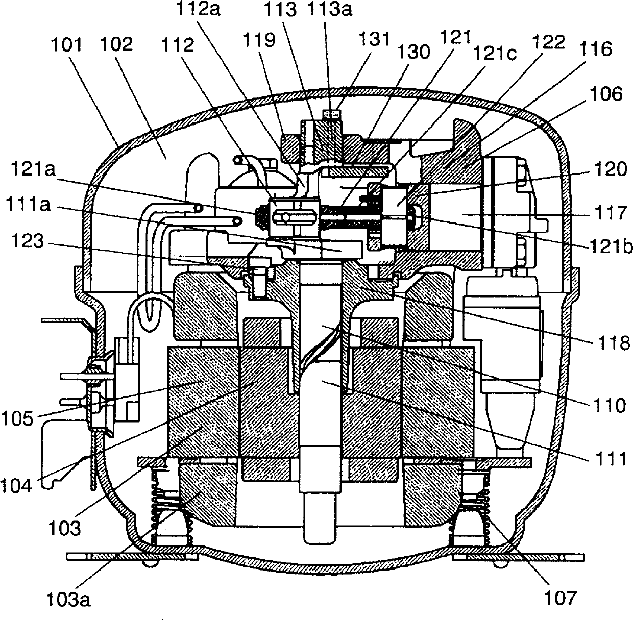
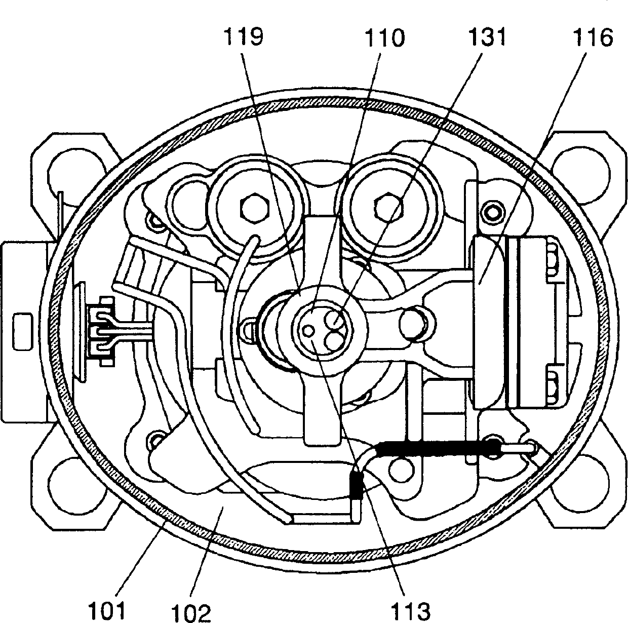
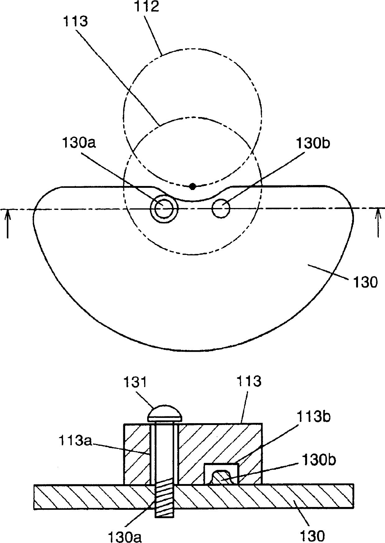
[0025] Fig. 1 is a vertical sectional view of a hermetic compressor according to a preferred embodiment 1 of the present invention. Fig. 2 is a horizontal sectional view of this embodiment. Fig. 3 is an expanded view of the main body of this embodiment. Figure 4 is a perspective view of the body of this embodiment. Fig. 5 is a sectional view of the main body of this embodiment.

[0026] In FIGS. 1 to 5 , the airtight container 101 is filled with refrigerant 102 . The electric element 105 is composed of a stator 103 and a rotor 104 including a coil portion 103a. The compression element 106 driven by the electric element 105 and the electric element 105 are elastically held in the airtight container 101 by the suspension spring 107 .

[0027] The shaft 110 has (i) a main shaft portion 111 in which the rotor 104 is pressed and fixed, (ii) an eccentric shaft portion 112 formed with a certain degree of eccentricity with respect to the main shaft portion 111, (iii) an eccentric ...

Embodiment 2

[0047] Fig. 6 is a perspective view of a main body of a hermetic compressor according to a preferred embodiment 2 of the present invention. 7 is a sectional view of a main body of a hermetic compressor according to Embodiment 2. FIG.

[0048] The basic structure of the hermetic compressor in this preferred embodiment 2 is the same as that indicated in FIGS. 1 to 5 . Also, for the same structures as some structures in Preferred Embodiment 1, the same symbols will be used, and detailed explanations thereof will be omitted.

[0049] In FIGS. 6 and 7 , the first counterweight 130 of the hermetic compressor is fixed to the subshaft portion 113 by pressing with rivets 151 .

[0050] An explanation will be given below of the method of assembling the hermetic compressor constructed as described above.

[0051] The piston 120 is integrated with the coupling mechanism 121 by means of a piston pin 122 and then inserted into the compression chamber 117 of the cylinder block 116 . After...


PUM


Abstract

By adopting a construction in which a first balance weight is provided at the side end portion of the eccentric shaft portion of the auxiliary shaft portion and a second balance weight is provided at the side end portion of the eccentric shaft portion the main shaft portion, it becomes possible to provide sufficient first balance weight and second balance weight, without spoiling compact size of the compressor, enabling to reduce noise and vibrations.

Description

technical field [0001] The present invention relates to a hermetic compressor used in refrigerators, air conditioners, refrigeration systems and the like. Background technique [0002] In recent years, refrigeration systems, such as household refrigeration refrigerators, are strongly required to reduce power consumption and perform noiseless operation. In such an environment, the use of low-viscosity lubricating oil and the reduction of the speed of inverter-driven compressors (about 1200r.p.m in the case of household refrigerators) are being gradually carried out. On the other hand, it is becoming a prerequisite to adopt hydrocarbon-based refrigerants, etc., which are natural refrigerants with a low greenhouse coefficient, represented by R134a and R600a whose ozone depletion coefficient is zero. Also, the conventional method of using both end bearings that support the shaft at not less than two points is effective as an element technique for reducing sliding loss and power...

Claims


Application Information

Patent Timeline
Patent Type & Authority Applications(China)
IPC IPC(8): F04B35/01F04B39/00F25B31/02
CPCF04B39/0094Y10S417/902F04B39/00F04B35/04F04B39/04
Inventor 垣内隆志小岛健
Owner PANASONIC CORP
Why Eureka
Try Eureka