
Instrument

A technology for instruments and instrument panels, which is applied in the field of instruments for automatic two-wheeled vehicles, and can solve problems such as impact, poor visual recognition, and inconvenient use

Active Publication Date: 2005-11-30
YAMAHA MOTOR CO LTD
View PDF0 Cites 7 Cited by
  • Summary
  • Abstract
  • Description
  • Claims
  • Application Information

AI Technical Summary

Problems solved by technology

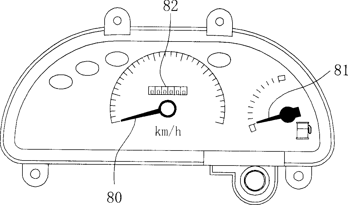
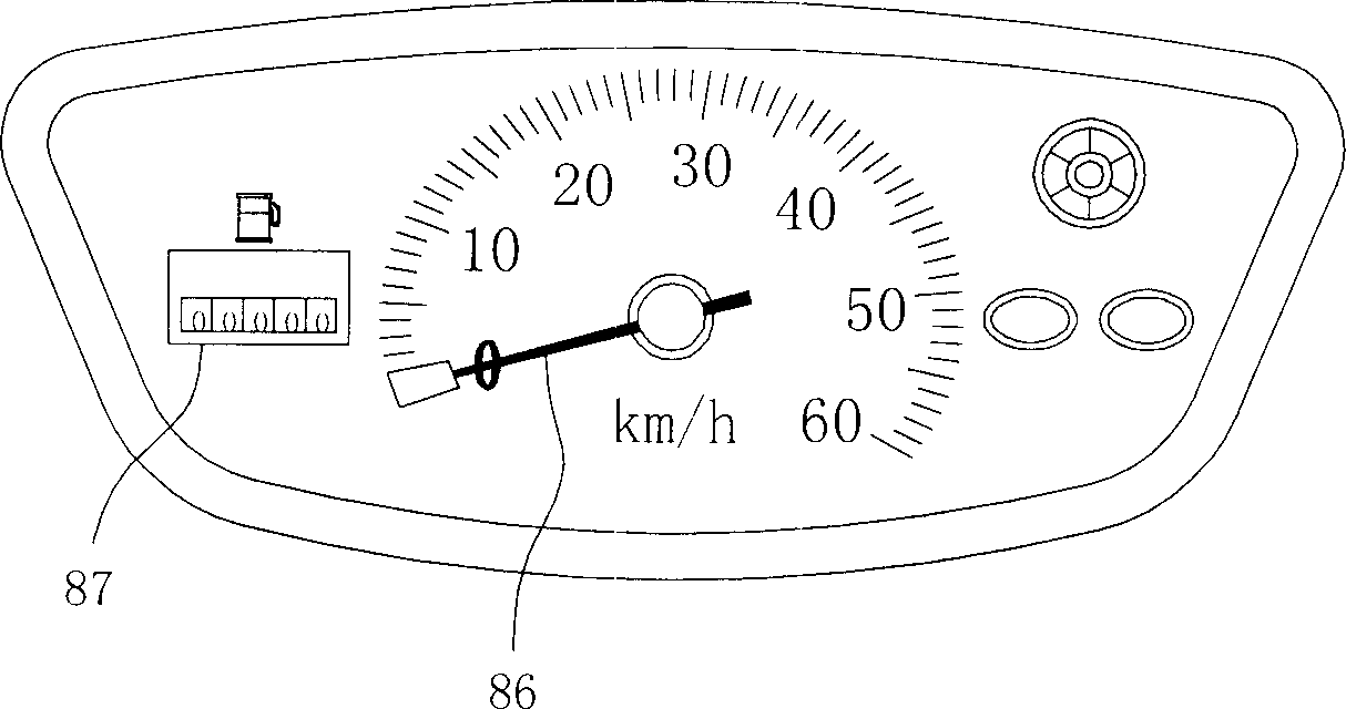
However, because the visual recognition of this kind of all-digital display instrument is poor, it is generally still arranged in an instrument in the form of a liquid crystal display and a pointer. It is necessary to avoid setting the liquid crystal display in the pointer identification area, and generally adopt the upper and lower or left and right separation (such as image 3 ) design method to achieve, so that the setting of the liquid crystal display and the pointer needs to occupy a larger area
[0006] see Figure 5 , which discloses another known meter for vehicles, which also uses a pointer 89 and a liquid crystal display 90 to display information at the same time. The liquid crystal display 90 is arranged in the area, and the driver can still see the information displayed by the liquid crystal display 90 through the transparent part 91 of the pointer 89. Although this kind of design can see the information displayed by the liquid crystal display 90 through the transparent part 91 of the pointer 89, but The shaking pointer 89 is located in front of the liquid crystal display 90, which will inevitably affect the driver's identification of the information on the liquid crystal display 90, and will still cause inconvenience in use.
[0007] Therefore, as can be seen from the above, the above-mentioned known instruments obviously have inconvenience and defects in actual use, and can be improved.

Method used


Image

  • Instrument
  • Instrument
  • Instrument

Examples


Embodiment Construction

[0056] see Image 6 and Figure 7 , the present invention provides a kind of pointer that does not have physical form, but is formed by indicating light 32 instrument, this instrument is the most suitable device for automatic two-wheel vehicle, and it comprises an instrument panel 10, a control part 20, A light source 30, a projector 40 and a drawing area 50, wherein a circuit board 11 is arranged below the instrument panel 10, a liquid crystal display (LCD) 12 is fixed on the circuit board 11, and the liquid crystal display 12 is electrically connected to the The circuit board 11, and the top of the liquid crystal display 12 is exposed on the surface of the instrument panel 10, so as to facilitate the identification of information on the liquid crystal display 12. The instrument panel 10 and the circuit board 11 can also be fixed at appropriate positions on the vehicle with a housing (not shown), so as to carry the above-mentioned components.

[0057] The control part 20 ca...


PUM


Abstract

This invention discloses an apparatus which comprises a light-accepting part with a mark zone, and an irradiation part ejecting light to the acceptor; wherein, the said irradiation direction can be changed, and the irradiation part primarily transforms the entity arrow into the fictitious one and casts light to the mark zone to provide distinguish effect. The arrow is un-visible and virtual between the light-accepting part and the irradiation part without any influence on distinguished zone to set liquid crystal display screen (LCD).

Description

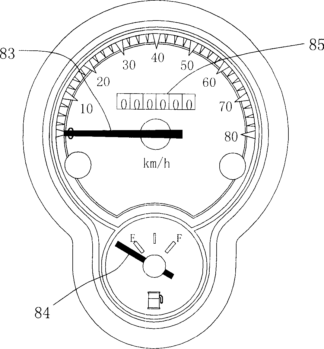
technical field [0001] The present invention relates to an instrument for an automatic two-wheeled vehicle, in particular to a design that transforms a physical pointer into a virtualized pointer, and projects light onto the depicting area (light-receiving part) to provide a recognition effect. The distance between the pointer light source and the depicting area is Invisible virtualized pointers without affecting the field of view setting Liquid Crystal Display (LCD) gauges. Background technique [0002] Automobiles and locomotives are one of the means of transportation commonly used by modern people. Instruments are installed on the vehicles to display various driving information (such as speed per hour, fuel volume, mileage, engine speed, temperature, etc.), so it is very important for drivers. Driving is very important. [0003] see figure 1 and figure 2 , Promptly disclose two kinds of known pointer gauges for vehicles, which mainly use pointers 80, 81 and 83, 84 to ...

Claims


Application Information

Patent Timeline
IPC IPC(8): G01D13/00
Inventor 许芳毓
Owner YAMAHA MOTOR CO LTD
Learn More