Outdoor three-position switch operating mechanism

A three-position switch and operating mechanism technology, applied in electrical switches, contact operating parts, contact driving mechanisms, etc., can solve the problems of difficulty in selecting the contact position, adding position confirmation contacts, etc., and achieves a large contact surface, Easy to install, easy to set up

Pending Publication Date: 2022-04-29
HENAN PINGGAO GENERAL ELECTRIC CO LTD +1
View PDF1 Cites 0 Cited by
  • Summary
  • Abstract
  • Description
  • Claims
  • Application Information

AI Technical Summary

Problems solved by technology

[0007] The purpose of the present invention is to provide an outdoor three-position switch operating mechanism to solve the technical problem that

Method used


Image

  • Outdoor three-position switch operating mechanism
  • Outdoor three-position switch operating mechanism
  • Outdoor three-position switch operating mechanism

Examples


Embodiment 1

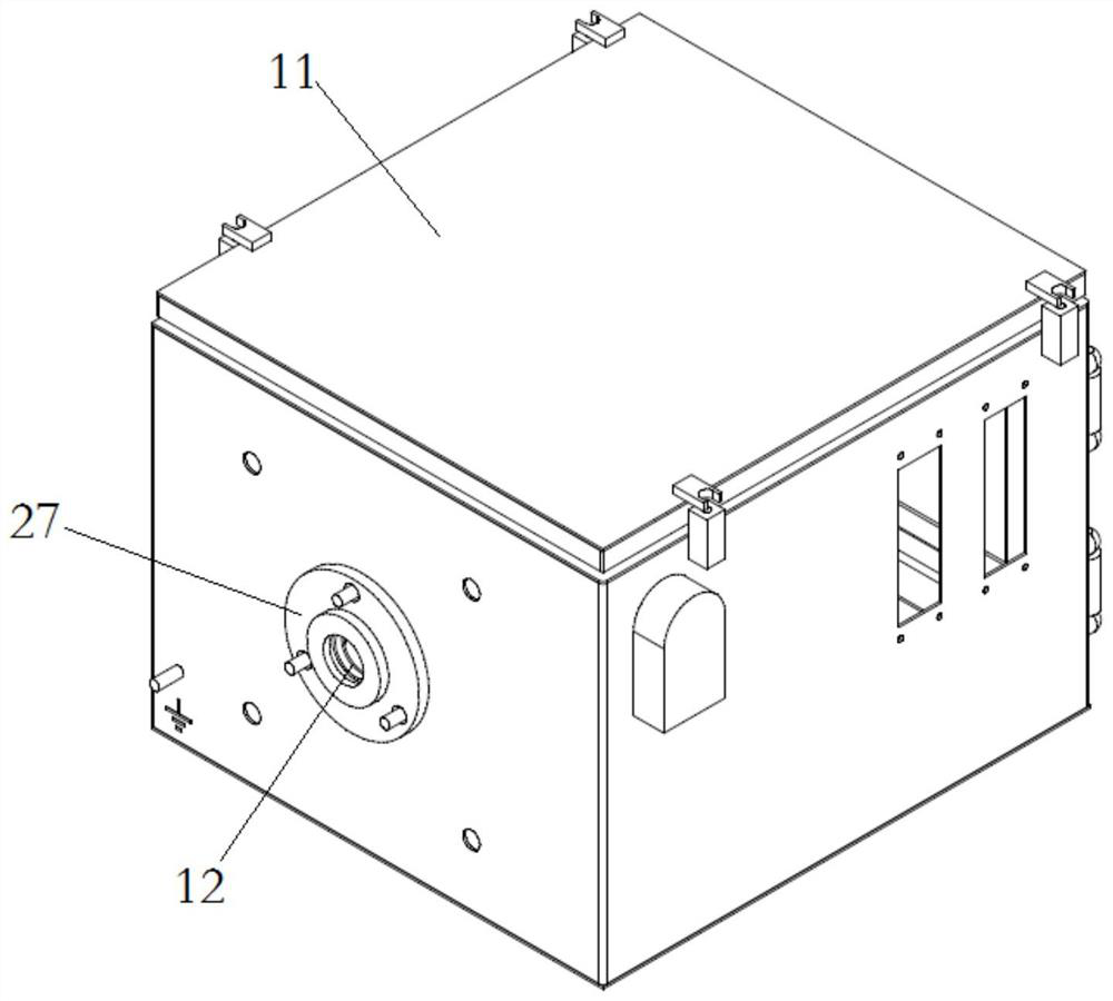
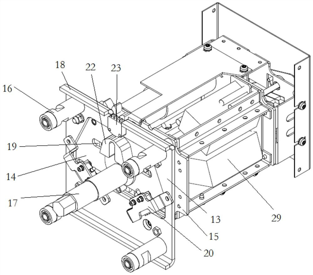
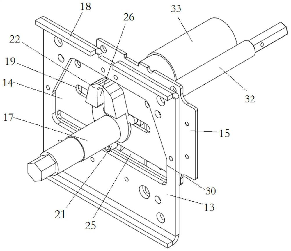
[0043] In this example, if Figure 1 to Figure 3 As shown, the outdoor three-position switch operating mechanism includes a protective box 11 and a mechanism body. The protective box 11 is a closed box for the mechanism body to fit into the outdoor environment. The protective box 11 is provided with a mechanism fixing plate 13 for the mechanism. The body is fixedly connected. Such as Figure 6 As shown, the mechanism body includes a transmission disc 31, which is engaged with the motor 33 gears for transmission. The transmission disc 31 is provided with a power transmission rod 32. On the mechanism connected to the transmission to provide a set of position confirmation contacts. The drive disc 31 is also provided with center-symmetrical guide pins opposite to each other. The guide pins are inserted into the switch chute with a specific profile on the switch slide 15 to drive the switch slide 15 to reciprocate. The switch sliding plate 15 behind the base plate 14 and the str...

Embodiment 2

[0051] The difference between this embodiment and Embodiment 1 is that in Embodiment 1, the thickened part is arranged at the overhanging end of the driving crank arm 22, and the microswitch 23 corresponding to the middle position corresponds to the extreme end of the driving crank arm 22, corresponding to the end of the driving crank arm 22. The microswitches 23 corresponding to the grounding position and the isolation position correspond to the two sides of the thickened part respectively. In this embodiment, the positions of the microswitches of the grounding position and the isolation position are changed so that the extreme end of the rotating driving crank arm respectively presses the micro switches corresponding to the middle position, the grounding position and the isolation position.

Embodiment 3

[0053] The difference between this embodiment and Embodiment 1 is that in Embodiment 1, the edge of the mechanism fixing plate 13 is provided with a forward folded edge 18, and the forward folded edge 18 is provided with an avoidance opening 28 for avoiding the position corresponding to the middle position. Micro switch 23. In this embodiment, an escape hole is provided directly above the mechanism fixing plate, and the escape hole is used for installing the installation support of the micro switch corresponding to the middle position.


PUM


Abstract

The invention relates to an outdoor three-position switch operating mechanism. The outdoor three-position switch operating mechanism comprises a substrate, a switch sliding plate is assembled on the substrate in a guiding mode, and a driving pin is arranged on the switch sliding plate. A forward overhanging mechanism output shaft is further rotationally assembled on the base plate, a driving connecting lever is fixed to the mechanism output shaft, and a driving guide groove extending in the radial direction of the mechanism output shaft is formed in the driving connecting lever; the driving pin penetrates into the driving guide groove so as to convert the guiding movement of the switch sliding plate into the swinging of the driving crank arm and the mechanism output shaft; the driving connecting lever is provided with a thickened part, and the thickness of the thickened part is larger than that of the part, connected with the mechanism output shaft, of the driving connecting lever. The outdoor three-position switch operation mechanism further comprises three microswitches which are fixedly arranged relative to the substrate, and contacts of the microswitches are used for corresponding to the thickened parts of the driving connecting lever and are respectively used for being triggered by the thickened parts when the mechanism output shaft is in a grounding position, a middle position and an isolation position.

Description

technical field [0001] The invention relates to the field of outdoor three-position switches, in particular to a "two-position" confirmation structure of an outdoor three-position switch operating mechanism. Background technique [0002] The three-position switch includes a switch body and an operating mechanism. For example, in the three-position switch operating mechanism of CN1050217C medium-voltage switchgear, the motor and the gear on the transmission disc are engaged for transmission. There are center-symmetrical and opposite guide pins on the transmission disc. The guide pin is inserted into the switch chute with a specific profile of the switch slide behind the drive plate to convert the rotational motion of the drive plate into the guide movement of the switch slide. ;The base plate is rotatably equipped with a forward-hanging mechanism output shaft, on which a driving crank arm is fixed, and a driving guide groove extending radially along the mechanism output shaft...

Claims


Application Information

Patent Timeline
IPC IPC(8): H01H3/32H01H3/02H01H9/02
CPCH01H3/32H01H3/02H01H9/02
Inventor 高正付王韶辉赵辉阎志朋秦悦悦侯宾宾高钰张俊李振中王贺军马雪曼
Owner HENAN PINGGAO GENERAL ELECTRIC CO LTD
Why Eureka
Try Eureka