Gas turbine combustor, and gas turbine with the combustor

A gas turbine and burner technology, which is applied in gas turbine installations, machines/engines, combustion chambers, etc., can solve problems such as combustion vibration that cannot be completely solved at the same time

Inactive Publication Date: 2005-12-07
MITSUBISHI HEAVY IND LTD
View PDF2 Cites 27 Cited by
  • Summary
  • Abstract
  • Description
  • Claims
  • Application Information

AI Technical Summary

Problems solved by technology

Therefore, it is effective for combustion vibration in the high frequency range, but can

Method used


Image

  • Gas turbine combustor, and gas turbine with the combustor
  • Gas turbine combustor, and gas turbine with the combustor
  • Gas turbine combustor, and gas turbine with the combustor

Examples


Embodiment Construction

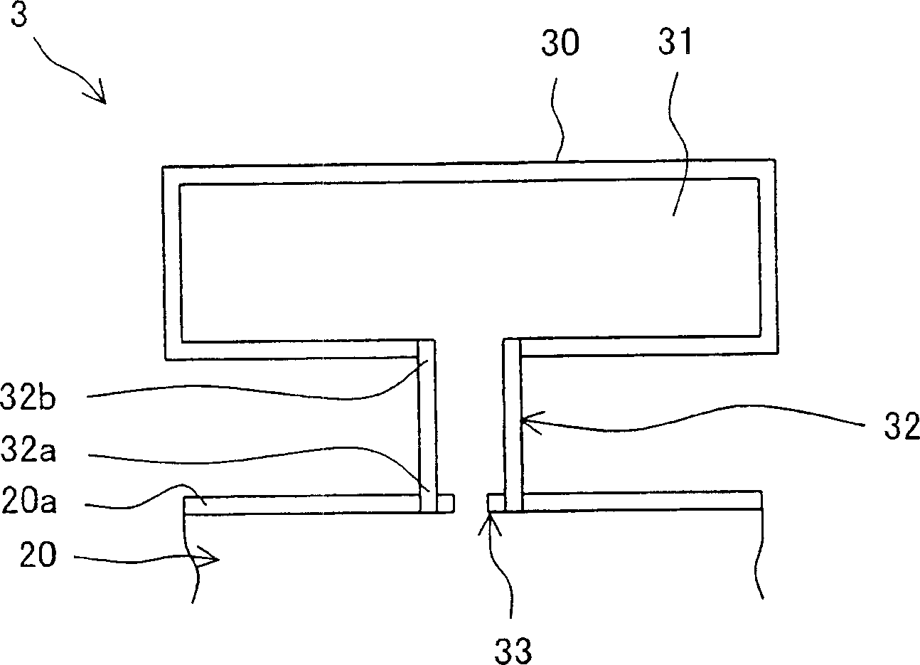
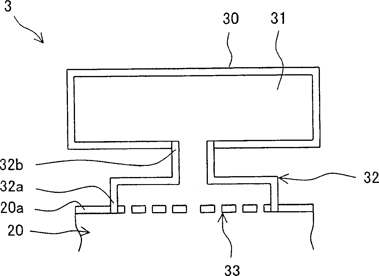
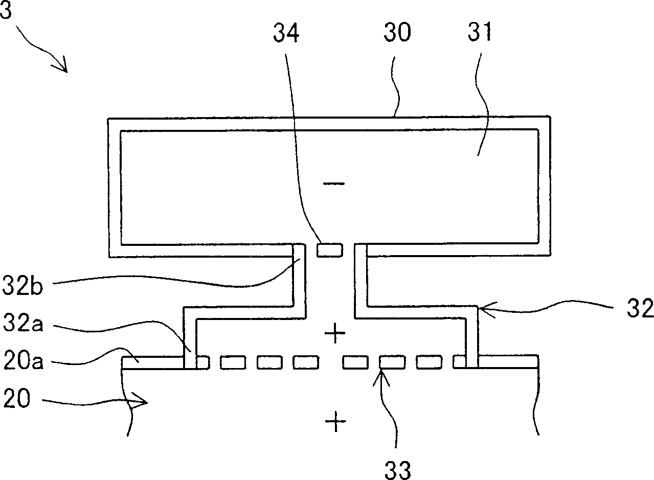
[0066] Now, embodiments of the present invention will be described below with reference to the drawings. First, the first to eighth embodiments of the present invention will be described page by page. figure 1 It is a cross-sectional view showing the configuration of the burner according to the first embodiment of the present invention. In the figure, the same mark means that it has Figure 47 For the parts with the same name and the same function, the same explanation will be omitted. The same applies to the second to eighth embodiments of the present invention which will be described below.

[0067] The burner 3 according to the first embodiment of the present invention is applied to Figure 47 Gas turbine 1 shown in. Such as figure 1 As shown in the figure, a first box 30 is installed outside the side wall 20a of the target body 20, and a first internal space 31 having a predetermined volume is formed by a cavity inside the first box 30. In addition, the first box body 30 is ...


PUM


Abstract

A gas turbine combustor (3) capable of reducing combustion vibration to stably reduce NOx, comprising a first box body (30) disposed on the outside of an objective body (20) having an inner tube (6), a tail tube (7), and a bypass duct (11) and forming a first internal space (31) of a specified volume and a first throat (32) of a specified length having one end (32a) opening to the side wall (20a) of the objective body (20) and the other end (32b) opening into the first internal space (31), wherein a first resistance body (33) having a large number of through-holes is fittedly inserted into one end (32a), fluid particles as vibration elements for the combustion vibration produced in a combustion area are effectively captured by the first resistance body (33) and resonated with air in the first internal space (31) connected thereto through the first throat (32) to vibrate near the first resistance body (33) so as to attenuate the amplitude of the vibration thereof.

Description

Technical field [0001] The present invention relates to a gas turbine combustor (hereinafter often referred to as a "burner") and a gas turbine equipped with a gas turbine combustor, and more particularly to a gas turbine combustor and a gas turbine that reduce combustion vibration so as to reduce nitrogen oxides (NOx) . Background technique [0002] Conventionally, gas turbines have as main components an air compressor (hereinafter often referred to as "compressor"), a combustor and a turbine, where the combustor is installed between the compressor and the turbine that are directly connected to each other through a main shaft; air is used as the working fluid Through the rotation of the main shaft, it is sucked into the compressor and compressed there; compressed air is introduced into the combustor and burned with fuel; high temperature and high pressure gas is discharged into the turbine to rotate the main shaft of the driving turbine. The gas turbine constructed in this way i...

Claims


Application Information

Patent Timeline
IPC IPC(8): F23R3/02F02C7/24
CPCF23R2900/00014
Inventor 池田和史万代重实川田裕青山邦明小野正树田中克则
Owner MITSUBISHI HEAVY IND LTD
Why Eureka
Try Eureka