Method and system for signal synchronization between receiver-transmitter and instrument

A transceiver and signal synchronization technology, applied in transmission systems, synchronization devices, digital transmission systems, etc., can solve the problems of high cost and small scope of application, and achieve the effect of reducing implementation costs and expanding the scope of application

Active Publication Date: 2010-12-08
LEADCORE TECH
View PDF2 Cites 0 Cited by
  • Summary
  • Abstract
  • Description
  • Claims
  • Application Information

AI Technical Summary

Problems solved by technology

[0015] The purpose of the present invention is to provide a method and system for synchronizing signals between transceivers and instruments, so as to solve the problem in the prior art that a special interface needs to be set on the transceiver, or even an additional clock conversion board is added to complete the transceiver. Signal synchronization between the machine and the instrument, that is, there are technical problems of small application range and high cost

Method used


Image

  • Method and system for signal synchronization between receiver-transmitter and instrument
  • Method and system for signal synchronization between receiver-transmitter and instrument
  • Method and system for signal synchronization between receiver-transmitter and instrument

Examples


no. 1 example

[0063] Taking the second monotone signal output by the transmitter as an analog signal as an example, the realization process of the present invention is described.

[0064] see Figure 6 , Figure 6 It is a structural schematic diagram of the first embodiment of the system for realizing signal synchronization between the receiver and the instrument during the testing process.

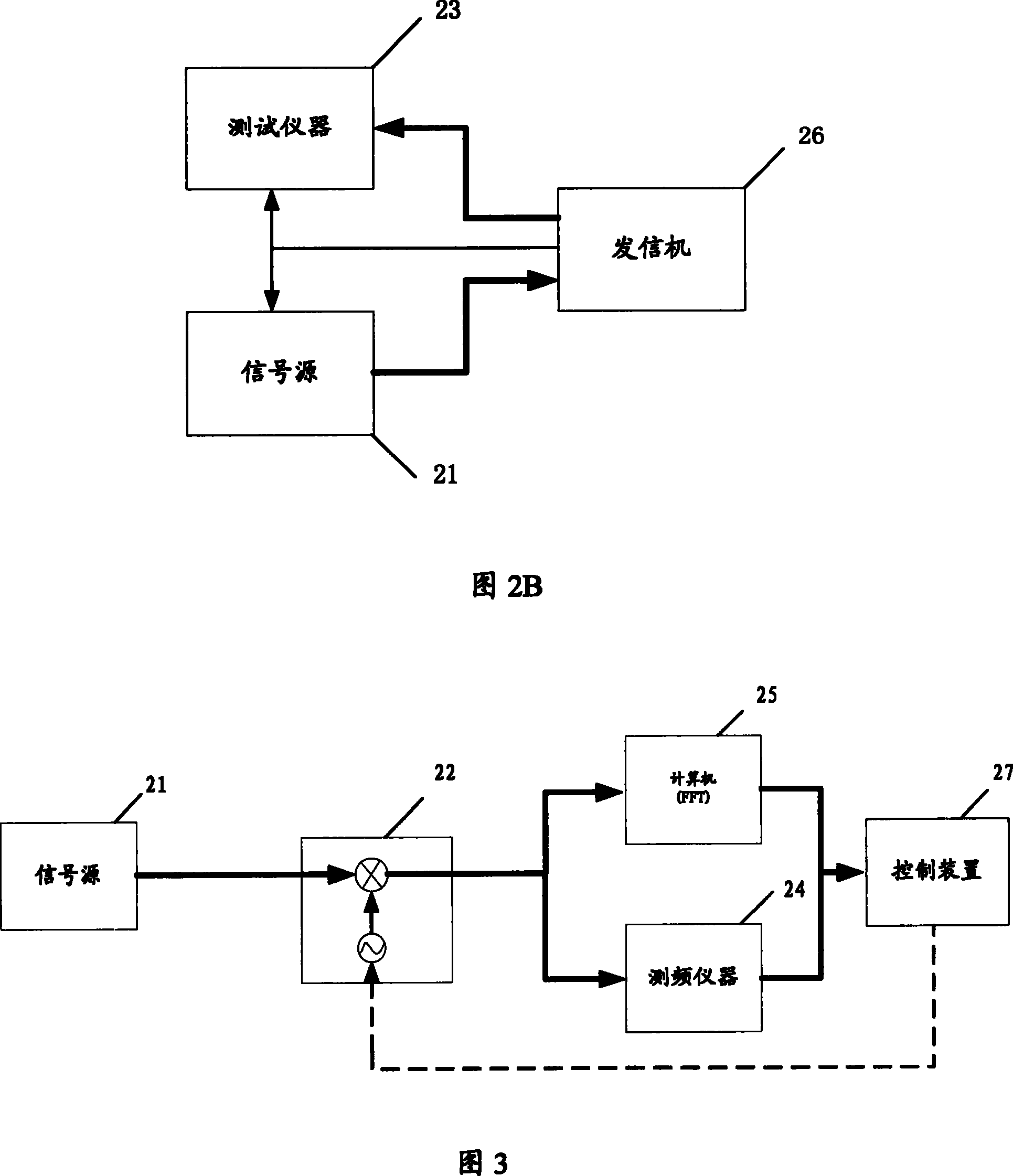
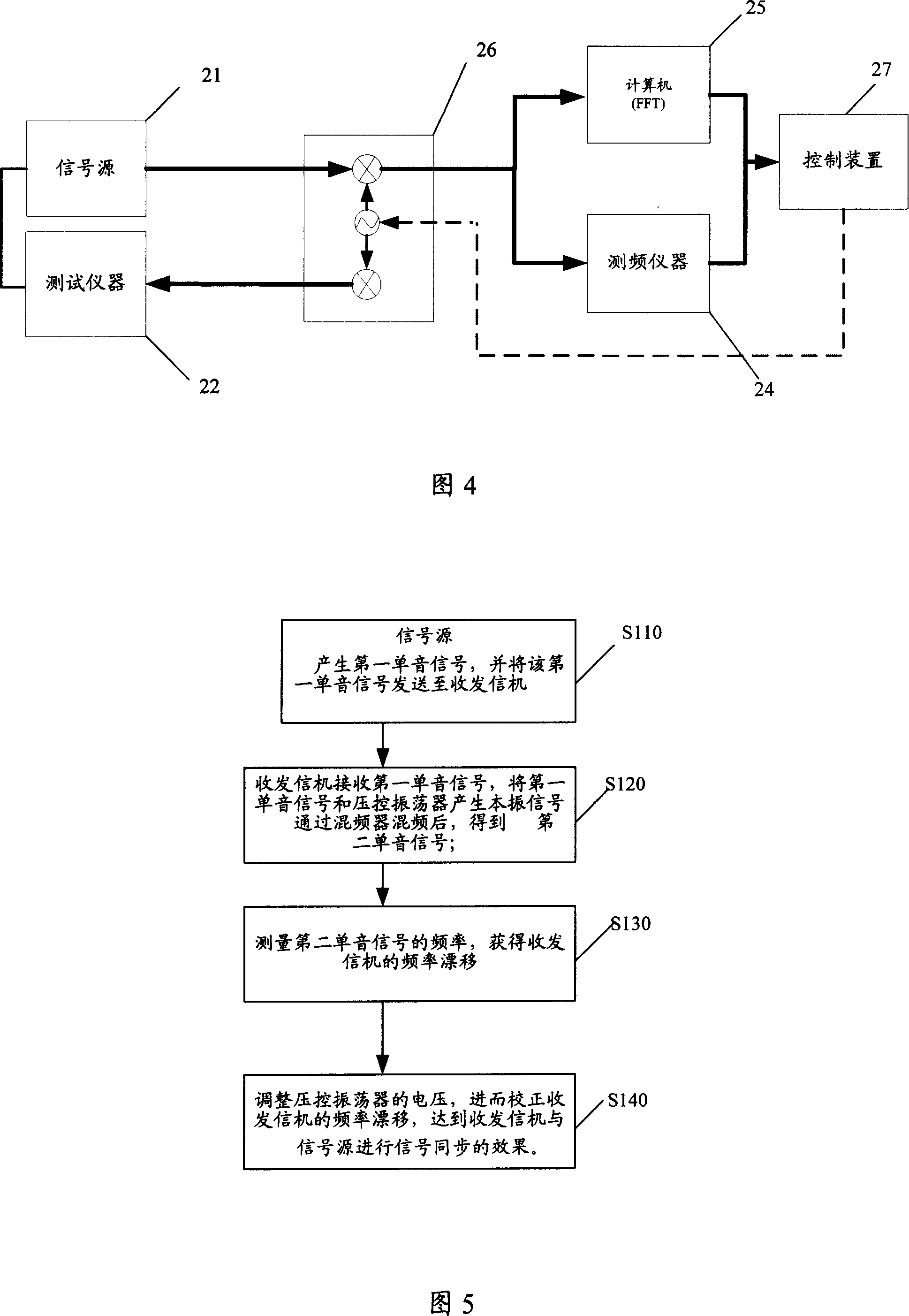
[0065] The system includes a signal source 21 , a receiver 22 , a frequency measuring instrument 24 , and a computer 25 . in:

[0066] Signal source 21: generating a first monotone signal;

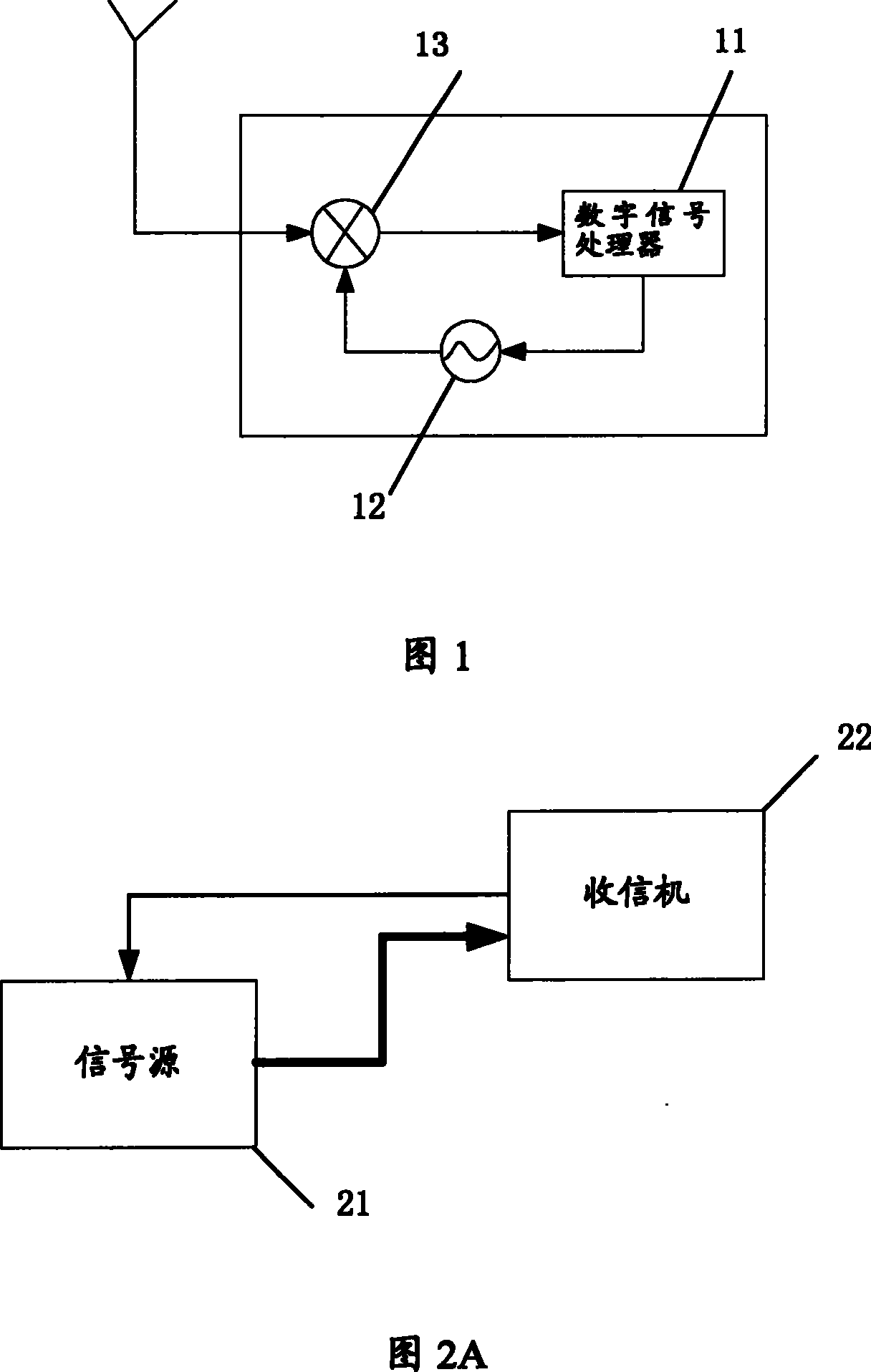
[0067] Receiver 22: The receiver 22 is a structure of direct frequency conversion, and the structure is relatively simple. It is connected to a signal source 21, including a voltage-controlled oscillator 12 for generating a local oscillator signal, a mixer 13, a DAC (digital-to-analog converter) 15, a band-pass filter 17, an amplifier (PA) 18, and a low-pass filter 14 , Amplifier 19.

[0068] The receiver 22...

no. 2 example

[0084] Taking the second tone signal output by the receiver as a digital signal as an example, the implementation process of signal synchronization between the receiver and the instrument in the testing process of the present invention will be described in detail below.

[0085] Please refer to Figure 9 , Figure 10 , Figure 9 It is a structural schematic diagram of the second embodiment of the system for realizing the signal synchronization between the receiver and the instrument during the testing process of the present invention. Figure 10 It is a schematic diagram of the structure of a computer.

[0086] It is the same as the first embodiment, which will not be repeated here. It differs from the first embodiment in that:

[0087] When the signal output by the receiver 22 is a digital signal, the frequency of the signal cannot be directly obtained by the frequency measuring instrument, but an FFT control module 34 can be set on the computer 25 to sample the digital s...


PUM


Abstract

The present invention discloses the method and system for synchronizing the transceiver and the instrument. The instrument includes signal source, and the transceiver includes voltage controlled vibrator to generate the local vibration signal and frequency mixer. The method includes: A. for the signal source to generate one first monotonic signal and to send the signal to the transceiver; B. for the transceiver to receive the first monotonic signal, to mix the first monotonic signal and the local vibration signal to generate the second monotonic signal; C. to measure the frequency of the second monotonic signal and to obtain local vibrator drift frequency through calculation with certain formula; and D. to regulate the voltage to the voltage controlled vibrator to correct the frequency drift of the said transceiver. The present invention can synchronize the transceiver and the instrument without need of increasing any hardware interface, and has low cost and wide application range.

Description

technical field [0001] The invention relates to the field of wireless communication, in particular to a method and a system for realizing signal synchronization between a transceiver and an instrument during a testing process. Background technique [0002] In most wireless communication devices, coherent demodulation is usually used to make the operating frequencies of the transmitting and receiving parties have the same frequency and phase. However, due to the own characteristics of the oscillator in the wireless communication device, the frequency will drift with time and the external environment (such as temperature, etc.), resulting in a frequency deviation. Therefore, it is necessary to correct the frequency drift of the oscillator. [0003] The above-mentioned equipment mainly includes a transceiver, and the transceiver includes a receiver and a transmitter. When communicating between two devices, if the transmitter of one device is synchronized with the receiver of t...

Claims


Application Information

Patent Timeline
Patent Type & Authority Patents(China)
IPC IPC(8): H04B17/00H04B1/46H04L7/00
Inventor 佟笑言樊峰邹勇
Owner LEADCORE TECH
Why Eureka
Try Eureka