
Lifting device of dyeing mechanism for flat screen printing machine

A screen printing machine and lifting device technology, applied to screen printing machines, printing machines, rotary printing machines, etc., can solve problems such as large difference in rebound force, difficulty in obtaining rebound force, difficulty in responding flexibly and quickly, and achieve Effects of smooth lifting operation and smooth motion characteristics

Active Publication Date: 2005-12-28
TOSHIN IND CO LTD
View PDF0 Cites 4 Cited by
  • Summary
  • Abstract
  • Description
  • Claims
  • Application Information

AI Technical Summary

Problems solved by technology

[0003] However, the above-mentioned compression springs have the following problems: due to the constraints of the installation space, it is difficult to obtain the expected rebound force, especially, the difference in the rebound force between the lower limit position and the upper limit position is large, and in the case of load fluctuations, It is necessary to change the compression springs of different sizes or change the number of installations, so it is difficult to respond flexibly and quickly. In particular, the table where the aforementioned printing and dyeing mechanism is installed becomes longer, etc. When the aforementioned compression springs increase, it becomes difficult to respond quickly
[0004] In addition, there is also the problem that the movement characteristics are not smooth due to the friction of the rails used to prevent the compression spring from flying out during movement

Method used


Image

  • Lifting device of dyeing mechanism for flat screen printing machine
  • Lifting device of dyeing mechanism for flat screen printing machine
  • Lifting device of dyeing mechanism for flat screen printing machine

Examples


Embodiment Construction

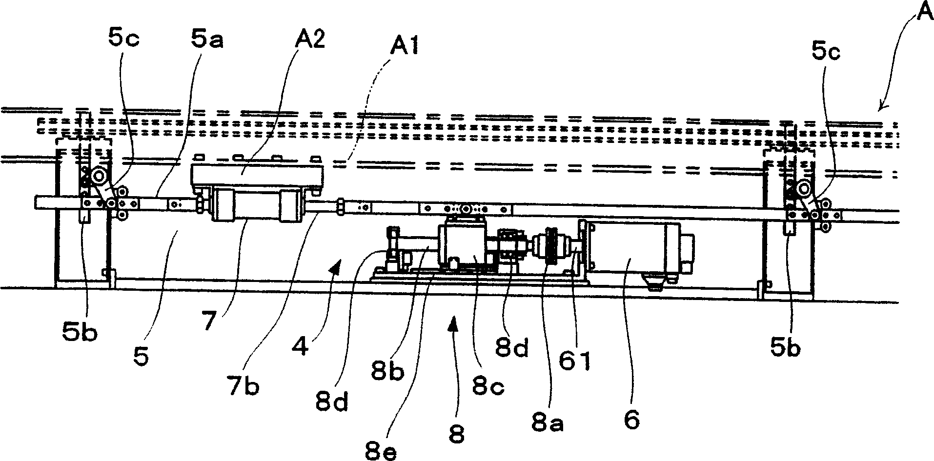
[0019] Such as figure 1 and figure 2 As shown, the flat screen printing machine has: an endless belt 2 erected between pulleys 1 in order to convey cloth and other printed objects, a printing and dyeing mechanism 3 with a screen frame, a printing and dyeing mechanism lifting device 4, and a control mechanism for controlling them ( illustration omitted).

[0020] Such as image 3 As shown, the printing and dyeing mechanism lifting device 4 includes: a lifting mechanism part 5, a servo motor (drive source) 6, and a power auxiliary mechanism 7 for assisting the driving force of the servo motor 6 for lifting the printing and dyeing mechanism 3, which are respectively arranged on the endless belt. 2 on both sides of the circular direction. in addition, figure 2 Indicates the state of raising the printing and dyeing mechanism 3, figure 1 Indicates the state in which the printing and dyeing mechanism 3 is lowered.

[0021] The elevating mechanism unit 5 includes: an operating...


PUM


Abstract

The invention provides a printing and dyeing mechanism elevating device of a flat screen printing machine that can quickly respond to changes in the load of the printing and dyeing mechanism. It is characterized in that it includes a lifting mechanism part for lifting and lowering the printing and dyeing mechanism and its driving source, and a power auxiliary mechanism for assisting the driving force of the driving source for raising the printing and dyeing mechanism; the power auxiliary mechanism is composed of a cylinder with the following mechanism: Mechanism composition: a cylinder, a piston rod, and two air chambers inside the cylinder that are divided by the piston area. The air supply mechanism makes the two air chambers generate a pressure difference and adjusts the pressure adjustment mechanism for the pressure difference; The pressing force of the piston rod generated by the pressure difference acts on the lifting mechanism to generate auxiliary power.

Description

technical field [0001] The invention relates to the lifting device of the printing and dyeing mechanism of an automatic plane screen printing machine which is equipped with one or more printing and dyeing mechanisms and performs single-color or double-color printing and dyeing on the printed matter sent in a certain amount. Background technique [0002] This printing and dyeing mechanism lifting device also has such a device: the compression spring assembled under the printing and dyeing mechanism is used as an auxiliary power mechanism. The rebound force of the spring makes it function as an auxiliary power. [0003] However, the above-mentioned compression springs have the following problems: due to the constraints of the installation space, it is difficult to obtain the expected rebound force, especially, the difference in the rebound force between the lower limit position and the upper limit position is large, and in the case of load fluctuations, It is necessary to cha...

Claims


Application Information

Patent Timeline
IPC IPC(8): B41F15/14
CPCE05D3/06E05F1/12E05F3/20E05Y2201/484
Inventor 一瀬四郎冈重树松下俊宏
Owner TOSHIN IND CO LTD
Learn More