Eureka AIR delivers breakthrough ideas for toughest innovation challenges, trusted by R&D personnel around the world.

Manuscript pressing plate switch

A technology of original pressing plate and switch device, which is applied in printing device, electrography, optics, etc. It can solve the problems of difficult maintenance work, pinching of hands and arms, difficult assembly operation, etc., and achieves the effect of compact device

Active Publication Date: 2011-01-19
KEM HONGKONG
View PDF1 Cites 0 Cited by
  • Summary
  • Abstract
  • Description
  • Claims
  • Application Information

AI Technical Summary

Problems solved by technology

[0003] In the original pressing plate switch device with the above structure, when the contact glass is disassembled for maintenance, this kind of operation is actually performed, that is, the original pressing plate needs to be moved from 60° to 70° during the operation. Open to 90°, but the original pressing plate will fall down during the operation. In this way, in addition to making maintenance operations difficult, especially if the original pressing plate is equipped with an automatic original feeding device, and the weight When the original is heavy, the original pressure plate falls down with acceleration, and there is a risk of pinching the hand or arm.
[0004] Also, in this conventionally known device, when the original pressing plate is assembled on the device main body, since an elastic device works between the mounting member and the support member, the original pressing plate is relatively stable relative to the device. The main body is assembled in an open state, however, there is a problem that it is difficult to perform such an assembly operation if the original pressure plate is in an open state, especially when the weight of the original pressure plate is heavy.

Method used


Image

  • Manuscript pressing plate switch
  • Manuscript pressing plate switch
  • Manuscript pressing plate switch

Examples


Embodiment Construction

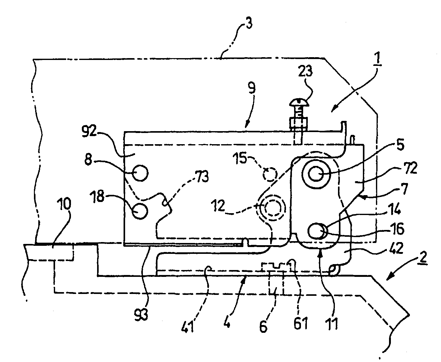
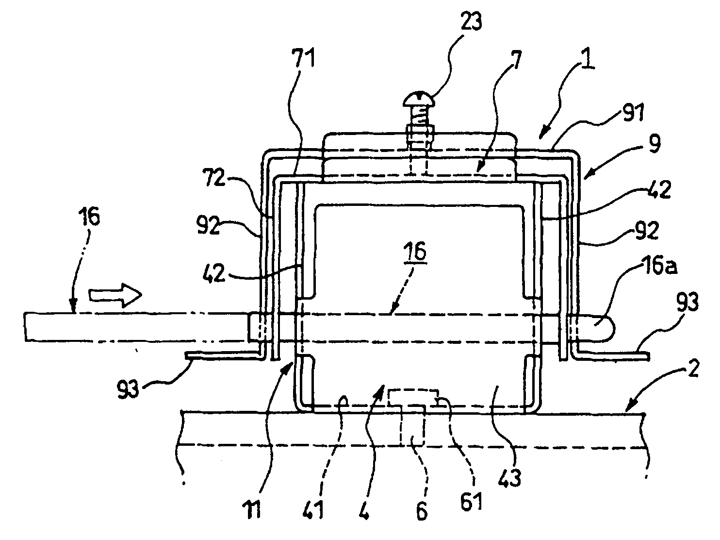
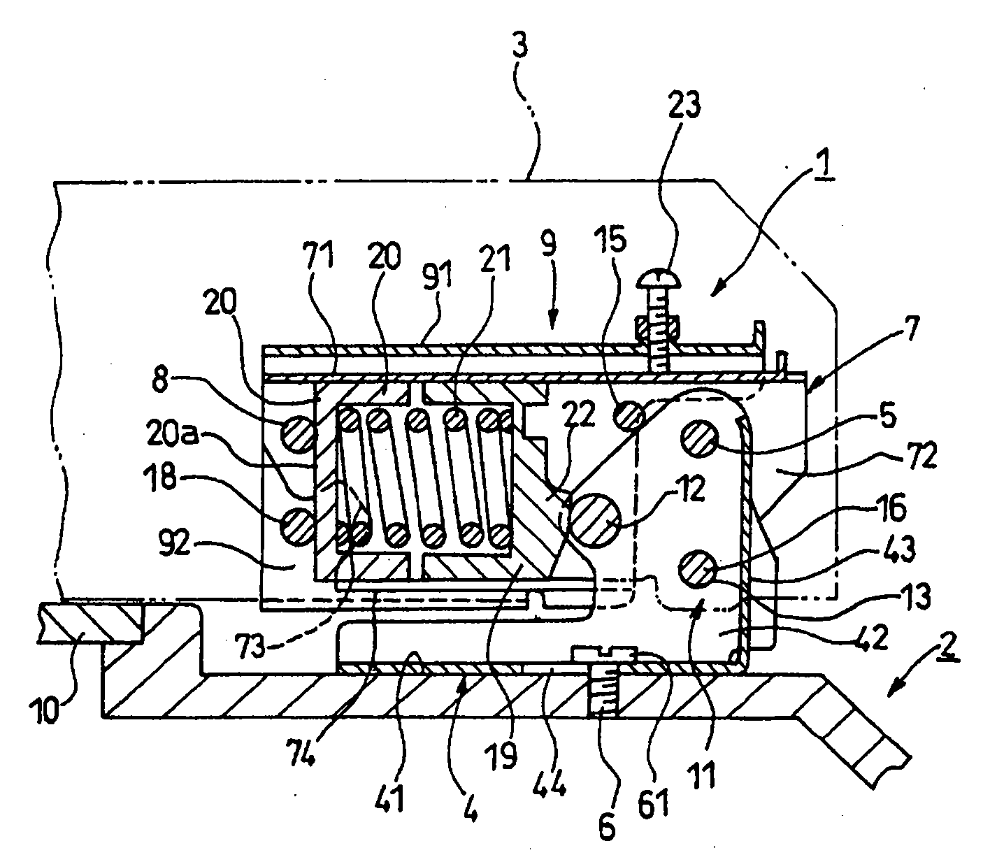
[0019] Next, the document pressure plate switching device of the present invention will be described in detail with reference to the accompanying drawings.

[0020] Figure 1 ~ Figure 3 It is an example of the document pressure plate switch device of the present invention. The original pressing plate switch device 1 of the present invention is a hinge mechanism installed on the device main body 2 of a copier, printing machine, facsimile machine, scanner, etc., which makes the original pressing plate 3 indicated by a phantom line face each other. The upper surface of the device main body 2 can be opened and closed. Such as Figure 1 ~ Figure 3 As shown, the original pressing plate switch device 1 of the present invention is composed of the following parts: the mounting part 4 is detachably installed on the rear upper end of the device main body 2 by installing the buckle part (taking and paying the buckle part material) 6; 7. It is rotatably connected to the mounting part 4 ...


PUM


Abstract

To provide an original cover opening / closing device capable of preventing an original cover from naturally falling even when the original cover is opened up to 90DEG C with reference to a device main body in the case of maintenance after the original cover is attached to the device main body, and constituted so that the original cover is easily assembled in the device main body. The original cover opening / closing device has a mount member attached to the device main body side, a supporting member for supporting the original cover and turnably attached to the mount member, and an elastic meanselastically installed between the mount member and the supporting member. It is provided with a turning preventing means capable of preventing the supporting member from turning at an opening angle at the maintenance time of the original cover or the closing angle of the original cover between the mount member and the supporting member.

Description

technical field [0001] The present invention relates to a document pressure plate switch device suitable for use in image forming apparatuses such as copying machines, printing machines, facsimile machines, and scanners. Background technique [0002] Conventionally, the structure of the known document pressure plate switch device is as disclosed in Patent Document 1 described below. The document pressure plate generates a rotational torque between the use opening angles from 0° to 60° to 70°. , but between the opening angles from 60° to 70° to 90°, no rotational torque is generated. The above-mentioned patent document is Japanese Patent Application Laid-Open No. 2000-31863. [0003] In the original pressing plate switch device with the above structure, when the contact glass is disassembled for maintenance, this kind of operation is actually performed, that is, the original pressing plate needs to be moved from 60° to 70° during the operation. Open to 90°, but the original...

Claims


Application Information

Patent Timeline
Patent Type & Authority Patents(China)
IPC IPC(8): G03B27/62
CPCG03G15/00G03G15/04G03G15/60H04N1/028H04N1/31
Inventor 铃木直和
Owner KEM HONGKONG
Why Eureka
Eureka Blog
Learn More