Paper transfer unit and image forming apparatus employing the same

A transmission unit and paper technology, applied in the direction of printing device, electric recording process using charge pattern, equipment for electric recording process using charge pattern, etc., can solve the problem of difficult paper conveying rate, etc.

Inactive Publication Date: 2006-02-22
SAMSUNG ELECTRONICS CO LTD
View PDF3 Cites 7 Cited by
  • Summary
  • Abstract
  • Description
  • Claims
  • Application Information

AI Technical Summary

Problems solved by technology

Therefore, it is more difficult to obtain an accurate paper transfer rate

Method used


Image

  • Paper transfer unit and image forming apparatus employing the same
  • Paper transfer unit and image forming apparatus employing the same
  • Paper transfer unit and image forming apparatus employing the same

Examples


Embodiment Construction

[0025] The matters defined in the specification, such as specific structures and elements, are provided to help comprehensive understanding of the embodiments of the present invention. Accordingly, those of ordinary skill in the art will recognize that many changes and modifications of the embodiments described herein can be made without departing from the spirit and scope of the invention. Also, descriptions of well-known functions and constructions are omitted for clarity and conciseness.

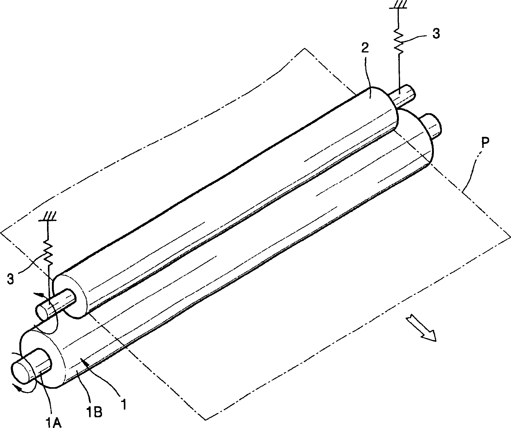
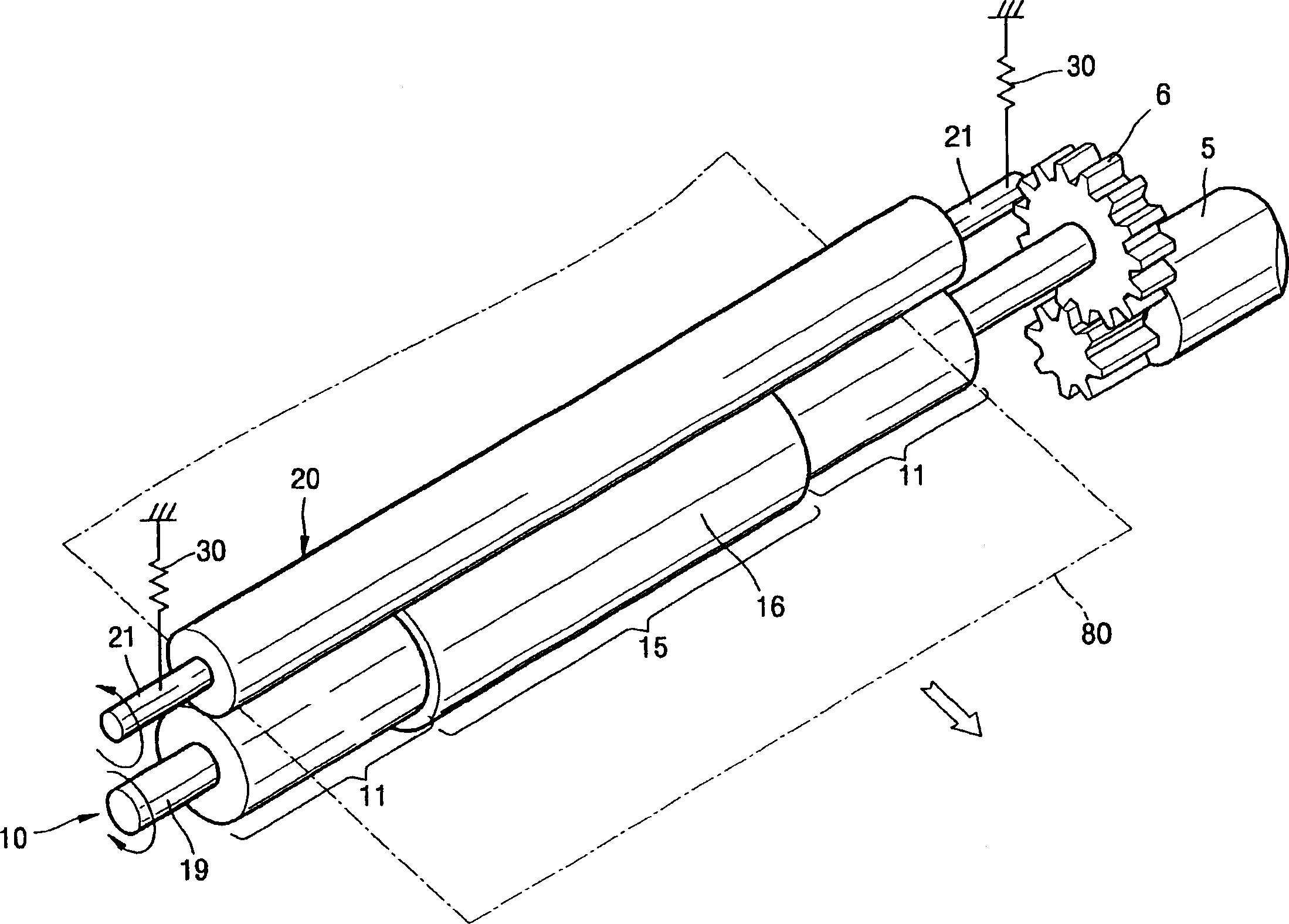
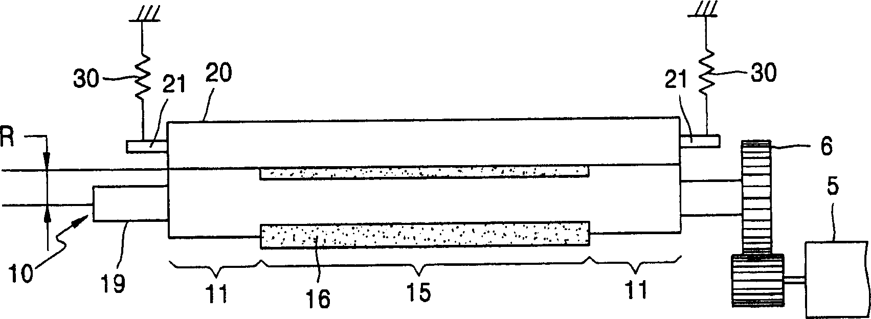
[0026] figure 2 with image 3 is a perspective view and a sectional view of a sheet conveying unit according to an exemplary embodiment of the present invention. refer to figure 2 with image 3 , the supply roller 10 meshes with the pinch roller 20 . The elastic member 30 biases the supply roller 10 and the pinch roller 20 toward each other for engagement. The elastic member 30 is preferably a compressed coil spring that pushes both ends 21 of the pinch roller 20 toward the supply...


PUM


Abstract

The present invention provides a paper transfer unit and an image forming apparatus employing the same. The paper transfer unit includes a pinch roller and a feed roller having a first outer portion, which defines a reference radius used to determine a paper transfer rate. A second outer portion is also provided having a substantially elastic rubber layer. An elastic element elastically biases the pinch roller and the feed roller toward each other.

Description

technical field [0001] The present invention relates to a sheet conveying unit and an image forming apparatus using the same. More particularly, the present invention relates to a paper conveying unit in which a pair of rollers are rollingly engaged with each other to convey a paper, and an image forming apparatus employing the paper conveying unit. Background technique [0002] figure 1 is a perspective view of a conventional sheet conveying unit. The driving roller 1 is driven by a motor (not shown), and the driven roller 2 contacts the driving roller 1 . The drive roller 1 includes a metal shaft 1A combined with a cylindrical rubber roller 1B. The elastic member 3 pushes the driven roller 2 toward the driving roller 1 . The outer surface of the driven roller 2 contacts the outer surface of the rubber roller 1B. The driving roller 1 and the driven roller 2 are in rolling engagement with each other. Paper P is conveyed between a driving roller 1 and a driven roller 2 ...

Claims


Application Information

Patent Timeline
Patent Type & Authority Applications(China)
IPC IPC(8): B41J11/00B41J11/04B41J13/076B41J15/04
CPCB65H2404/182B65H2404/1316B65H2404/143B41J13/076B41J13/025B65H27/00B65H5/062B41J13/02B65H2404/185B65H2513/40B65H2401/111B65H2404/144B65H2404/14B65H2404/5322B65H2220/03G03G15/0815G03G15/234G03G15/6552
Inventor 韩东勋孙明甫李龙德
Owner SAMSUNG ELECTRONICS CO LTD
Why Eureka
Try Eureka