Near-field optical storage reading equipment
A technology of reading equipment and near-field light, which is applied in the configuration/installation of the head, and can solve the problem of inaccurate access to the magnetic track
- Summary
- Abstract
- Description
- Claims
- Application Information
AI Technical Summary
Problems solved by technology
Method used
Image

Examples
no. 1 Embodiment
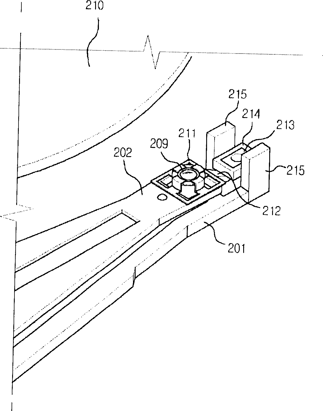
[0061] figure 2 It is the first embodiment of the present invention.
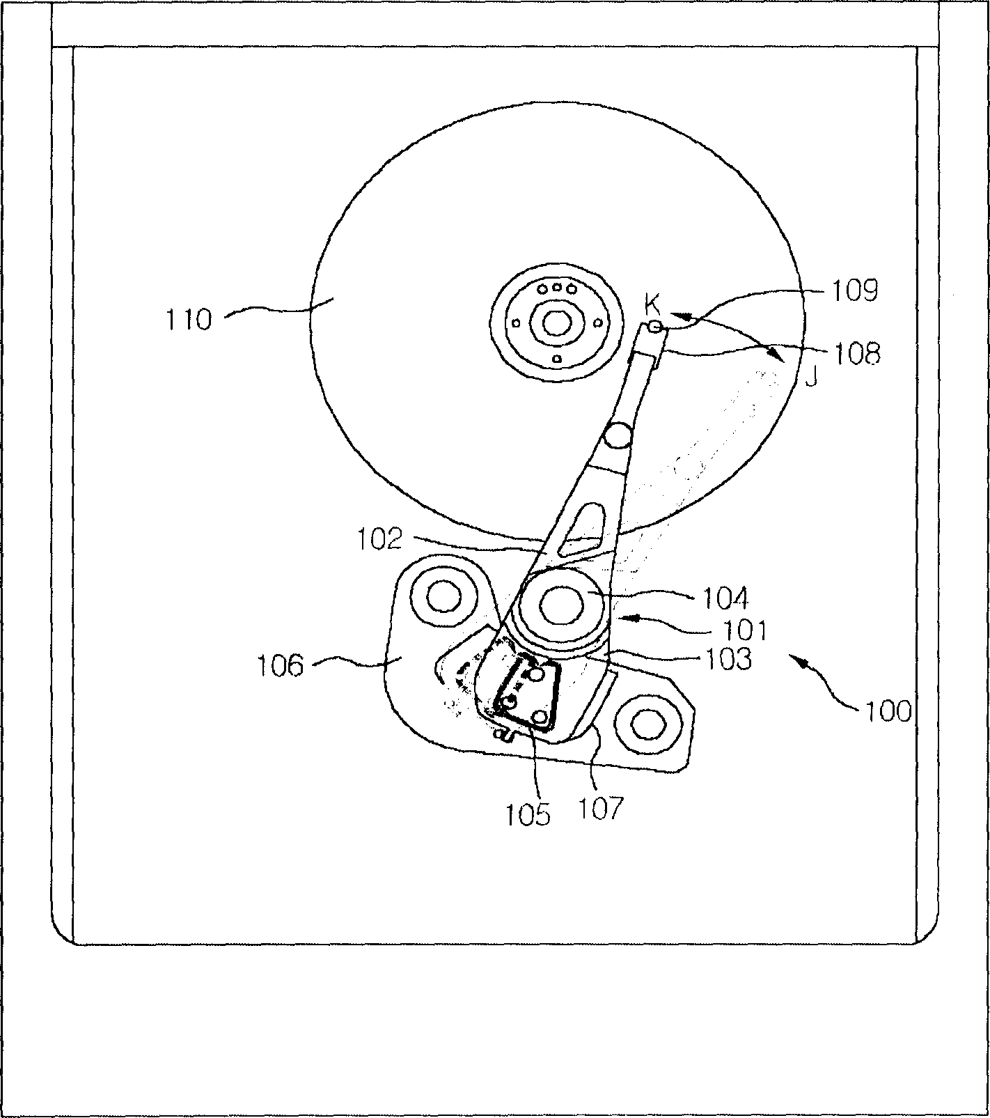
[0062] Such as figure 2 As shown, the adjuster arm 201 rotates along the direction of the magnetic track with reference to the rotation axis inserted in the center of the VCM. Here, the VCM consists of a track coil on the other side of the adjuster arm and a magnet on its lower base, and by supplying current to the track coil, the adjuster arm is rotated along the track direction with the rotation axis as a reference. (refer to figure 1 )
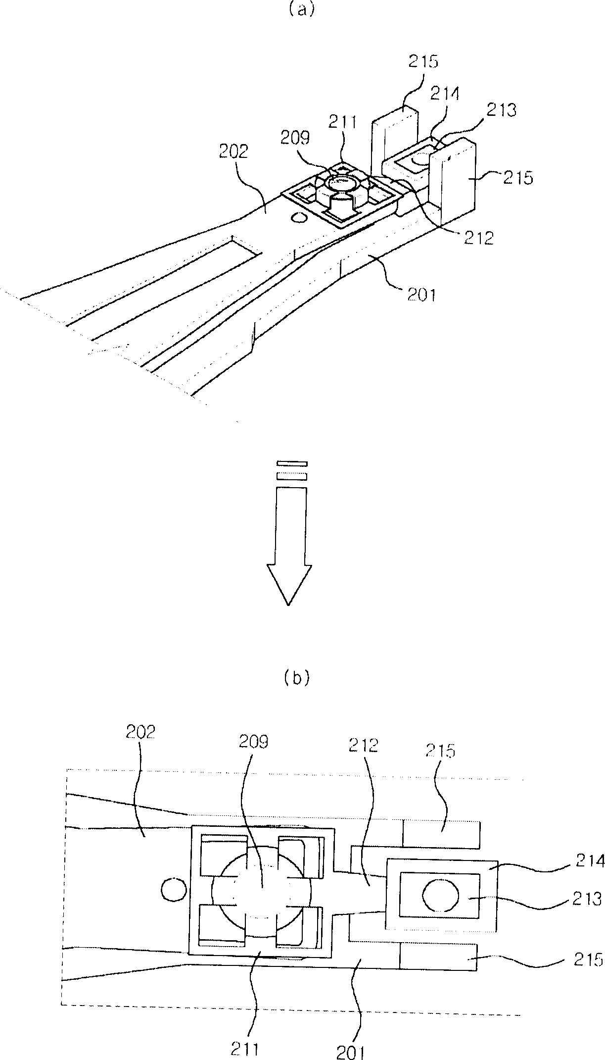
[0063] Such as figure 2 with image 3 As shown, on one side of the adjuster arm 201, a levitator 202 is synchronously arranged to move through a prescribed elastic action, and at the front end of the levitator 202, a pickup lens 209 is arranged.
[0064] The pickup lens 209 is fixed on the front end of the levitator 202 through the lens support frame 211, and the four iron pieces on the lens support frame 211 support the outer part above the pickup lens in the f...
no. 2 Embodiment
[0071] Figure 4 It is a diagram showing the second embodiment of the present invention. Wherein, (a) is a schematic diagram of the front end of the levitator, and (b) is a plan view thereof.
[0072] Such as Figure 4 (a) As shown in (b), on the other side of the regulator 301 that rotates the track through the VCM, a levitator 302 that moves through a prescribed elastic action is set, and a pickup lens 309 is set at the front end of the levitator 302 .
[0073] In order to wind the focusing coil 314 at the front end of the levitator 302, connect the lens support frame 311 and the extension frame 312 of the fixed pickup lens 309, and connect the extension frame 312 and the focus coil support part 313 into one, and follow the focusing The focus coil 314 is wound horizontally around the outer periphery of the coil support part 313 .
[0074] In addition, a focus magnet 315 is provided at the front end of the adjuster arm 301 at a position opposite to the back of the focus co...
no. 3 Embodiment ;
[0077] Figure 5 It is a figure showing the third embodiment of the present invention. Wherein, (a) is the figure shown at the front end of the levitator, and (b) is its plan view.
[0078] Such as Figure 5 (a) As shown in (b), at the front end of the suspension device 402 of the adjuster arm 401, the lens support frame 411 is used to fix the pickup lens 409, and the lens support frame 411 is integrated with the extension frame 412 having a certain length, so as to The end of the suspender 402 is extended. At the lower end of the extension frame 412, a focusing coil support part 414 is provided parallel to the base. In addition, the focus coil 414 is wound vertically along the outer periphery of the focus coil support portion 413, so that the surface or bottom of the optical disc is separated to a certain extent, forming a quadrangular shape.
[0079] On the bottom surface opposite to the focus coil 414 vertically wound on the focus coil support part 413, that is, along t...
PUM
 Abstract
Description
Claims
Application Information
 - R&D Engineer
- R&D Manager
- IP Professional
- Industry Leading Data Capabilities
- Powerful AI technology
- Patent DNA Extraction
Browse by: Latest US Patents, China's latest patents, Technical Efficacy Thesaurus, Application Domain, Technology Topic.
© 2024 PatSnap. All rights reserved.Legal|Privacy policy|Modern Slavery Act Transparency Statement|Sitemap