Optical disk driver with novel structure

A new type of structure, optical drive technology, applied in the direction of recording information storage, instruments, etc., can solve the problems of serious excitation force, optical disc 10 vibration, optical disc playback and recording, etc.

Inactive Publication Date: 2006-03-08
LEJIN GUANGDIAN ELECTRONIC CO LTD SHANGHAI
View PDF0 Cites 0 Cited by
  • Summary
  • Abstract
  • Description
  • Claims
  • Application Information

AI Technical Summary

Problems solved by technology

[0013] Due to such a space, the pressure unevenness of the optical drive becomes more serious, and since the pressure distribution of one rotation is relatively high and low, the excitation phenomenon occurs on the optical disc
In particular, when the magnification is high, its excitation force will become more serious, so it will cause serious vibration of the optical disc 10, and at the same time, it will have a negative impact on the playback and recording of the optical disc.

Method used


Image

  • Optical disk driver with novel structure
  • Optical disk driver with novel structure
  • Optical disk driver with novel structure

Examples


Embodiment Construction

[0033] Referring to the accompanying drawings, the structure, function and effect of the optical drive tray structure in the example of the present invention will be described in detail.

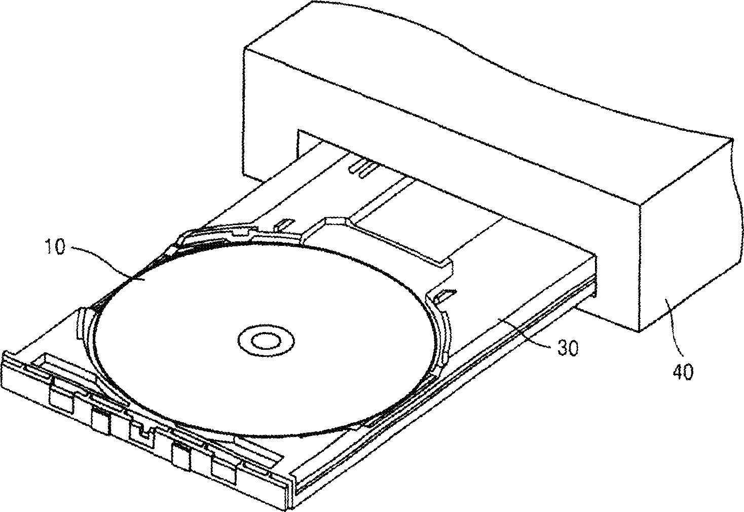
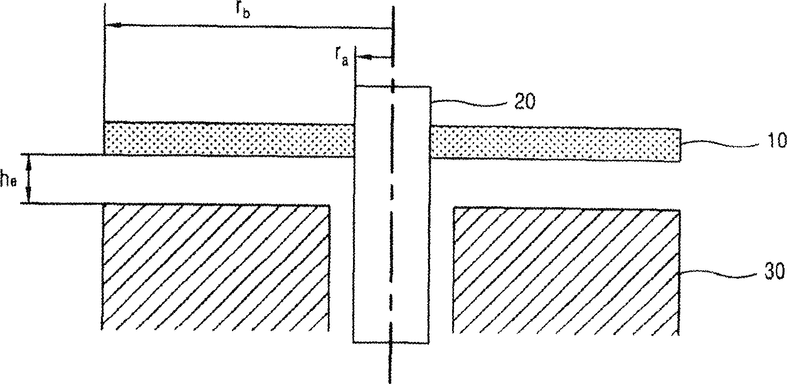
[0034] The optical drive among the present invention is made up of following parts: Tray 3, can accommodate optical disc 1 inside the casing, and move inside and outside the casing; The power drive shaft 2 is composed of an optical pick-up device for recording or playing optical information on the above-mentioned optical disc 1 rotating under the action of the drive device.

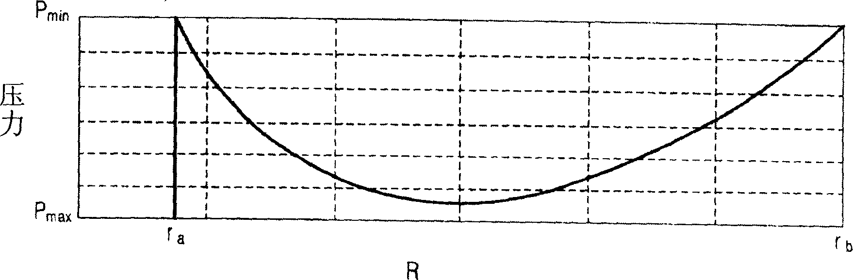
[0035] The above tray 3 as Figure 4 As shown, its bottom surface forms a streamline shape, and the distance between it and the bottom surface of the optical disk 1 changes along the radius.

[0036] The bottom surface of the above-mentioned tray 3 and the lower surface of the optical disc 1 maintain the same interval as in Mathematical Formula 2, and the gap obtained by Mathematical Formula 1 does not occur. figure ...


PUM


Abstract

The optical drive includes following parts: telescopic tray for housing optical disk inside chassis; drive for driving optical disk on the tray; recording on optical disk rotated under action of drive or optical pick-up for playing optical information. In the drive, gap between bottom of the tray and lower surface of optical disk can be changed based on radius. Thus, when optical disk is rotated in high speed, pressure gradient occurred between bottom of the tray and lower surface of optical disk is minimized. The invention makes optical disk be driven more stable so as to guarantee creditability of recorded and played information.

Description

technical field [0001] The invention relates to an optical drive for driving an optical disc. Background technique [0002] The general optical drive has been developed to the specifications of 52X recording above 10,000RPM, and the related CD series or DVD series discs are also continuously increasing their double speed. At the same time, many mechanical problems caused by the high-speed drive have also been caused. What we need are related countermeasures. [0003] According to Korean Patent No. 100298553000, taking the optical disc 10 rotating in the casing 40 as an example, compared with the upper and lower central positions, the vibration amount at the asymmetrical position of the up and down tilt is significantly lower. [0004] But CD-ROM such as figure 1 or figure 2 As shown, below the optical disc 10 is the tray 30, and above the optical disc 10 is the entire casing 40; the distance between the optical disc 10 and the upper casing 40 is more than three times the...

Claims


Application Information

Patent Timeline
IPC IPC(8): G11B17/035
Inventor 金南雄
Owner LEJIN GUANGDIAN ELECTRONIC CO LTD SHANGHAI
Why Eureka
Try Eureka