
Network resource management method

A network resource management and network resource technology, applied in the field of network resource management using state machines, can solve the problems of increased maintenance, low development efficiency, and lack of generalization of verification rules.

Inactive Publication Date: 2006-03-08
HUAWEI TECH CO LTD
View PDF0 Cites 9 Cited by
  • Summary
  • Abstract
  • Description
  • Claims
  • Application Information

AI Technical Summary

Problems solved by technology

[0031] 1) A lot of code is spent on conditional verification and state transition propagation. The more conditions and state transitions are propagated, the greater the amount of code. In fact, their coding modes are similar
This will lead to low development efficiency, a large number of bugs, and a corresponding increase in maintenance
[0032] 2) Any changes to state or state migration will cause these codes to be re-modified, thus introducing new bugs
[0033] 3) The verification rules are not summarized, the existing rules are not easy to be reused, and it is not easy to introduce new verification rules

Method used


Image

  • Network resource management method
  • Network resource management method
  • Network resource management method

Examples


Embodiment Construction

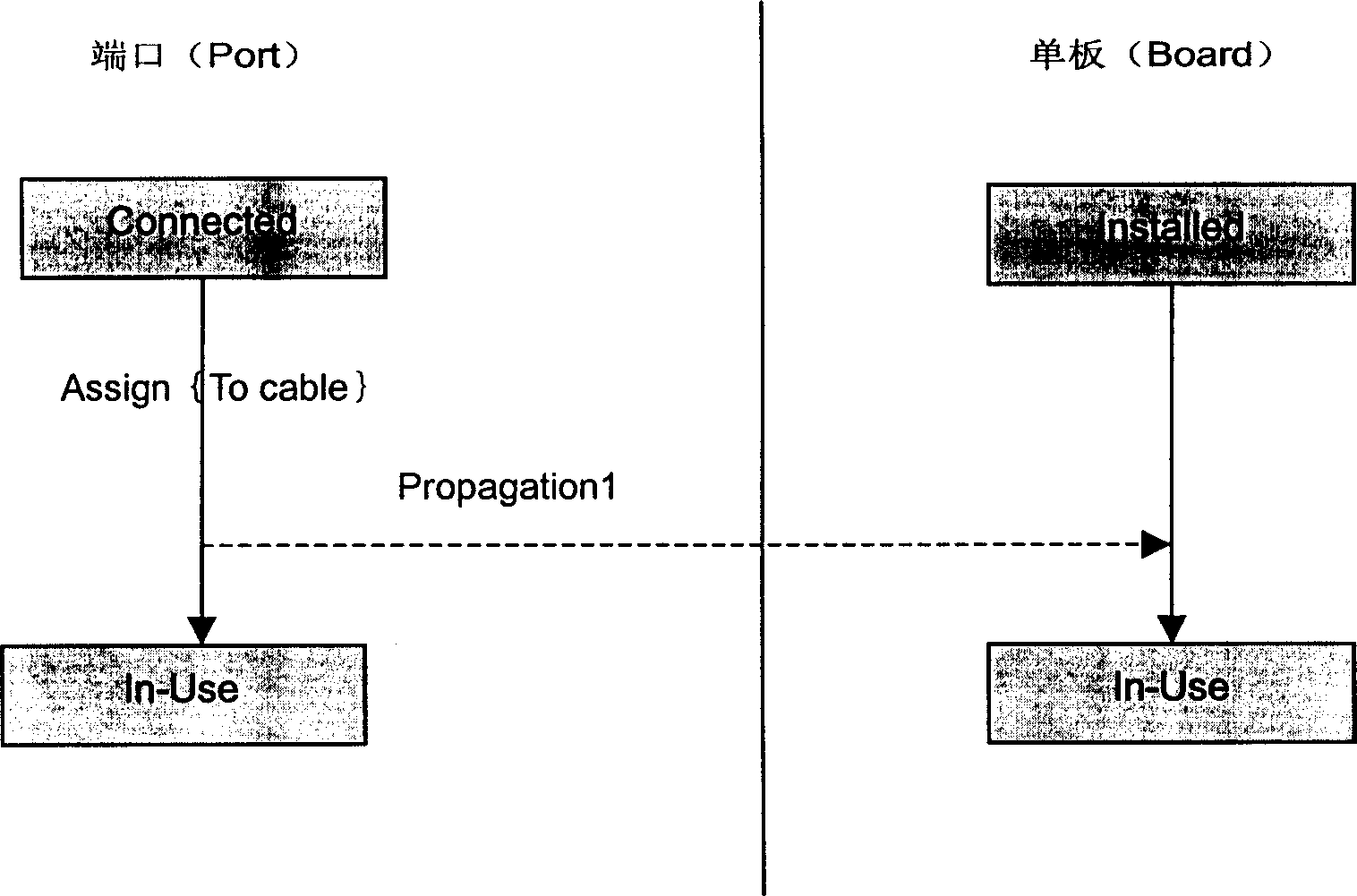
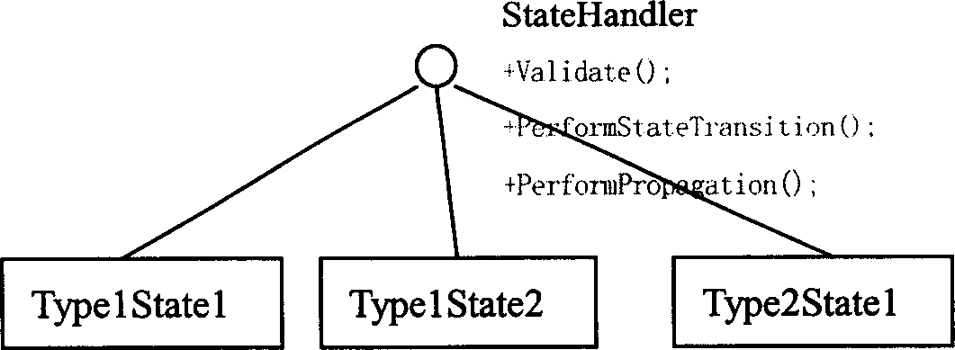
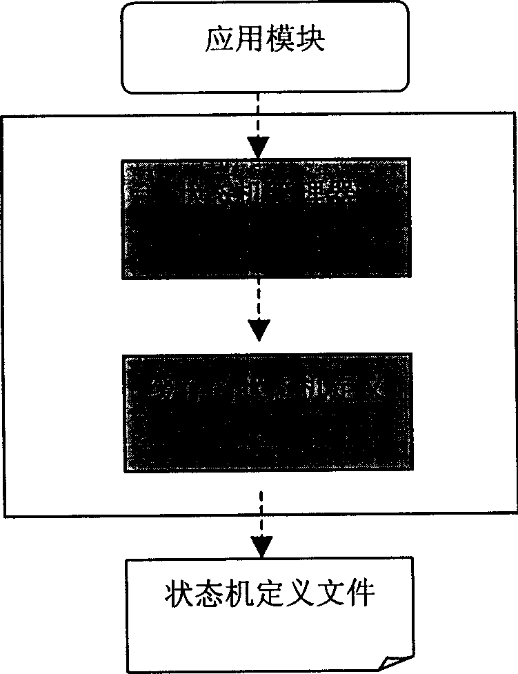
[0049] image 3 A general schematic block diagram of the software architecture for implementing the invention is shown.

[0050] In the present invention, the state machine is defined in the form of a state machine definition file, which is loaded into the memory when the system is initialized to form multiple groups of state machine entity objects; the state machine manager uses these entity objects and their relationships to provide application modules with The state machine handles the service; the application module uses the state machine service to determine whether the operation (event) can be executed, and what state to migrate to after the execution is completed. The following describes the detailed scheme of each part one by one from bottom to top.

[0051] Definition of state machine

[0052] Each network resource corresponds to a state machine. The definition of each state machine must first contain multiple state definitions of the resource. Each state has multip...


PUM


Abstract

Using tag language defines state machine of each network resource in a configuration file. The state machine includes states of corresponding network resource, at least one state migration associated to each state, event associated to each state migration, and at least one condition associated to each state migration. The method includes following steps: obtaining parameters of a event happened; obtaining condition of migration associated to the said event from the configuration file, and checking out whether the state migration associated to the event can be executed or not; if the checking up is passed, then state migration is executed.

Description

technical field [0001] The invention relates to a network resource management method, in particular to a method for using a state machine to manage network resources. Background technique [0002] In the field of network resource management, it is necessary to solve the state transition of entity objects and the state transition of associated objects caused by the state transition. [0003] A resource will go through multiple states during its life cycle, and the behavior of activating these state transitions is also different. The status types of each resource type are different. Even if different resource types have the same status name, the migration behavior of the status is not the same. For ease of understanding, some concepts used in the present invention are first introduced: [0004] 1) State (State) [0005] The state represents a relatively stable situation of a specific resource instance within a certain period of time, unless a change event (such as deletion,...

Claims


Application Information

Patent Timeline
IPC IPC(8): H04L12/24
Inventor 尼姆尤张治华
Owner HUAWEI TECH CO LTD
Learn More