Textile fabric structure and method for determining the interspacing of microelectronic elements of the textile fabric structure

A fabric structure, microelectronics technology, applied in the direction of fabrics, electrical components, circuit optical components, etc., can solve the problems of inflexibility, inappropriate production, and high cost.

Inactive Publication Date: 2006-03-22
INFINEON TECH AG
View PDF2 Cites 18 Cited by
  • Summary
  • Abstract
  • Description
  • Claims
  • Application Information

AI Technical Summary

Problems solved by technology

[0007] Specific methods such as these are inflexible and expensive, so they are not suitable for mass production in the market

Method used


Image

  • Textile fabric structure and method for determining the interspacing of microelectronic elements of the textile fabric structure
  • Textile fabric structure and method for determining the interspacing of microelectronic elements of the textile fabric structure
  • Textile fabric structure and method for determining the interspacing of microelectronic elements of the textile fabric structure

Examples


Embodiment Construction

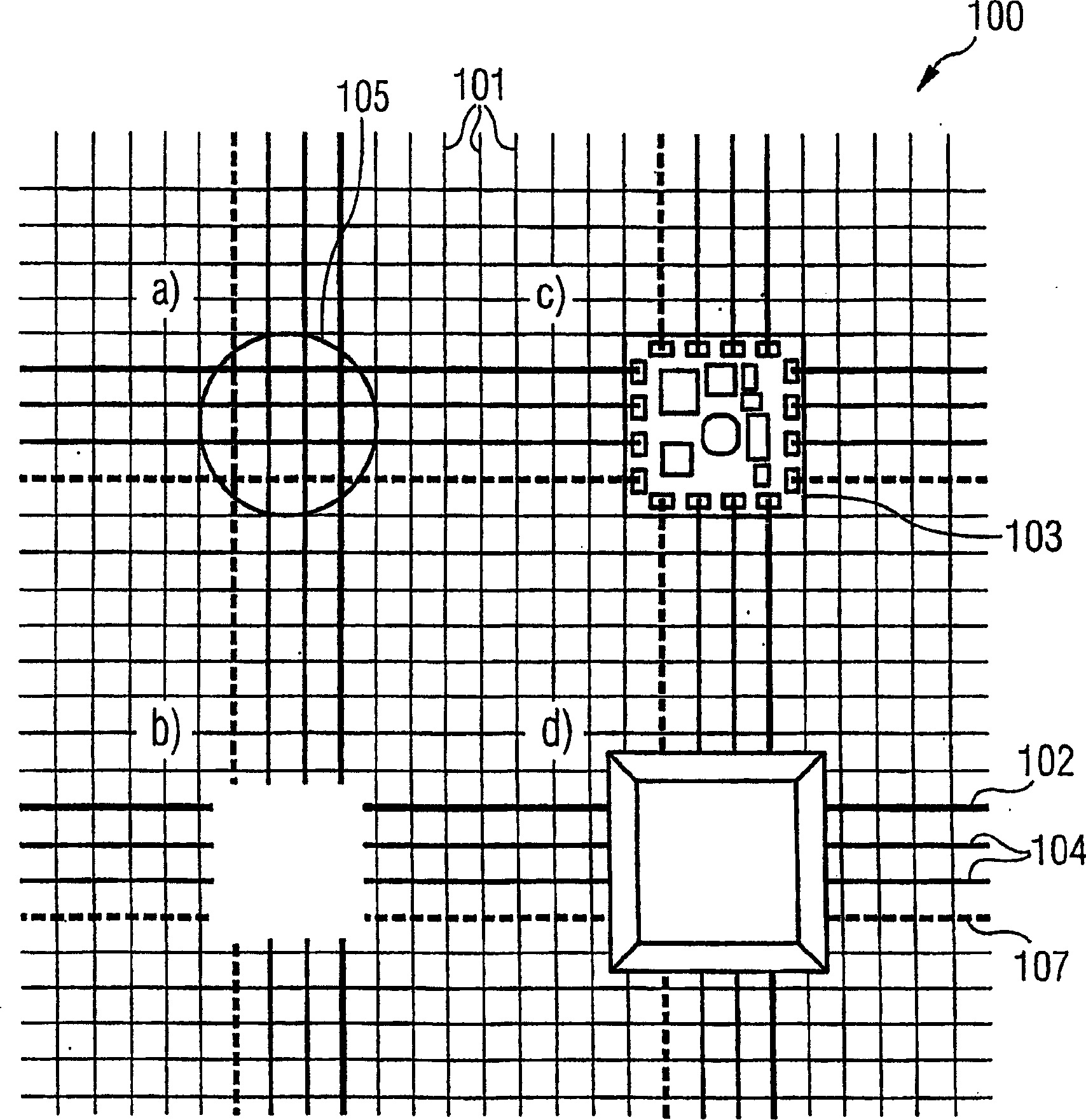
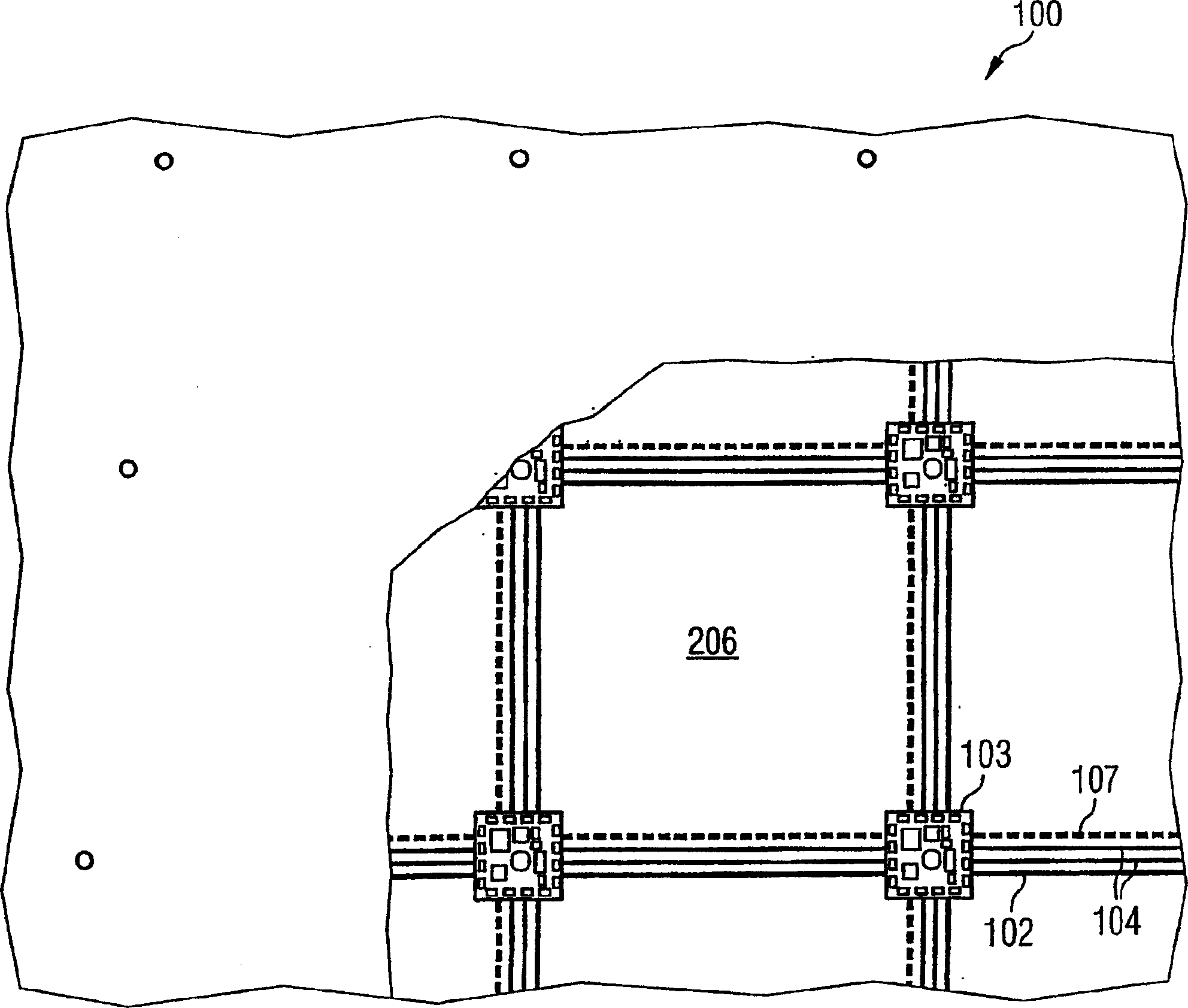
[0064] exist figure 1, a schematic illustration of a fabric structure according to a preferred embodiment of the present invention. The fabric structure 100 according to the present invention has a coarse-meshed fabric as a base structure on which non-conductive wiring 101 is formed. In addition, the textile structure 100 has electrically conductive connections 102 , 107 . The electrically conductive wire 102 serves as a ground wire for the microelectronic assembly 103 integrated on the fabric structure 100 . The electrically conductive wire 107 is used as a power supply circuit for the microelectronic component 103 integrated on the fabric structure 100 . In addition, the fabric structure 100 has conductive wires 104 for transmitting signals from the microelectronic components integrated on the fabric structure.

[0065] The electrically conductive wires 102, 107 and the conductive data transmission wires 104 are preferably placed on the fabric in the form of a grid of squ...


PUM


Abstract

The invention relates to a textile fabric structure having a plurality of microelectronic components, which are arranged in the textile fabric structure, electrically conductive threads, which couple the plurality of microelectronic components to one another, conductive data transmission threads, which couple the plurality of microelectronic components to one another, and electrically nonconductive threads. The conductive threads and the conductive data transmission threads at the edge of the textile fabric structure are each provided with an electric interface and a data transmission interface.

Description

technical field [0001] The present invention relates to a fabric structure, a surface covering structure and a method of determining the clearance of a microelectronic assembly relative to at least one reference position on the fabric structure. Background technique [0002] In many fields of construction technology and display structures, it is necessary to deploy sensor systems and actuator systems, especially display components, in a simple manner in floors, walls or ceilings. In such cases, the invention relates to touch and / or pressure on the floor, wall or ceiling which should be perceptible randomly or globally and should be able to react with an optical or audible indication of the presence of the touch and / or pressure. [0003] The desired large-area sensor system or large-area display system must be suitable for operation in a simple manner. In particular, the installation of the sensor system or actuator system should be suitable for floors, walls or ceilings of ...

Claims


Application Information

Patent Timeline
Patent Type & Authority Applications(China)
IPC IPC(8): D03D15/00A41D1/00D02G3/44
CPCD10B2401/20D03D15/0066D03D15/02H05K1/038Y10T442/30Y10T442/3976D03D1/0088D10B2401/16D02G3/441H05K1/00D10B2101/20D03D15/00D10B2503/04D10B2101/12H05K1/0274H05K3/284H05K2201/0281D03D15/258D03D15/67D03D15/547
Inventor R·H·J·格拉塞S·荣格C·劳特巴奇
Owner INFINEON TECH AG
Why Eureka
Try Eureka