Handle lifting mechanism chair type toilet

A lifting mechanism and handrail technology, which is applied to household appliances, applications, sanitary equipment, etc., can solve the problems of being clamped under the handrail, difficult for users to operate, and the number of parts increases, and achieves the effect of simple structure and low-cost manufacturing.

Inactive Publication Date: 2006-03-29
COMBI WELLNESS CORPORATION
View PDF3 Cites 5 Cited by
  • Summary
  • Abstract
  • Description
  • Claims
  • Application Information

AI Technical Summary

Problems solved by technology

[0006] However, in the above-mentioned inventions described in Patent Document 1 and Patent Document 2, the lock release mechanism for lowering the armrest is disposed on the side of the chair body below the armrest. When this happens, the lock release mechanism cannot be operated, so the chair-type toilet must be installed a little away from the bed, which will make it difficult for the user to transfer from the bed to the chair-type toilet.
[0007] In addition, in the invention described in Patent Document 1, the operation of the unlocking mechanism is a complicated operation of pulling the handle after unlocking, so there is also a problem that the user is difficult to operate.
[0008] In addition, in the inventions described in Patent Document 1 and Patent Document 2, when the armrest is lowered, there is a danger of pinching fingers under the armrest, and care must be taken when descending.
[0009] In addition, in the invention described in the aforementioned Patent Document 3, the armrest is raised and lowered by turning the locking operation lever in the horizontal direction and then holding the armrest to raise and lower the armrest, so the operation is complicated.
In addition, since the structure is complicated, the number of parts increases, resulting in an increase in cost

Method used


Image

  • Handle lifting mechanism chair type toilet
  • Handle lifting mechanism chair type toilet
  • Handle lifting mechanism chair type toilet

Examples


Embodiment Construction

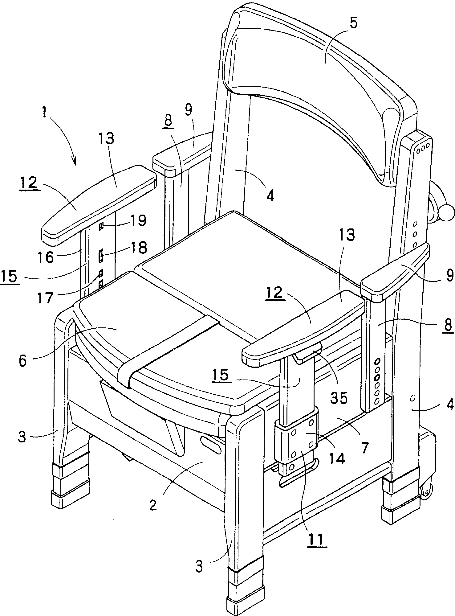
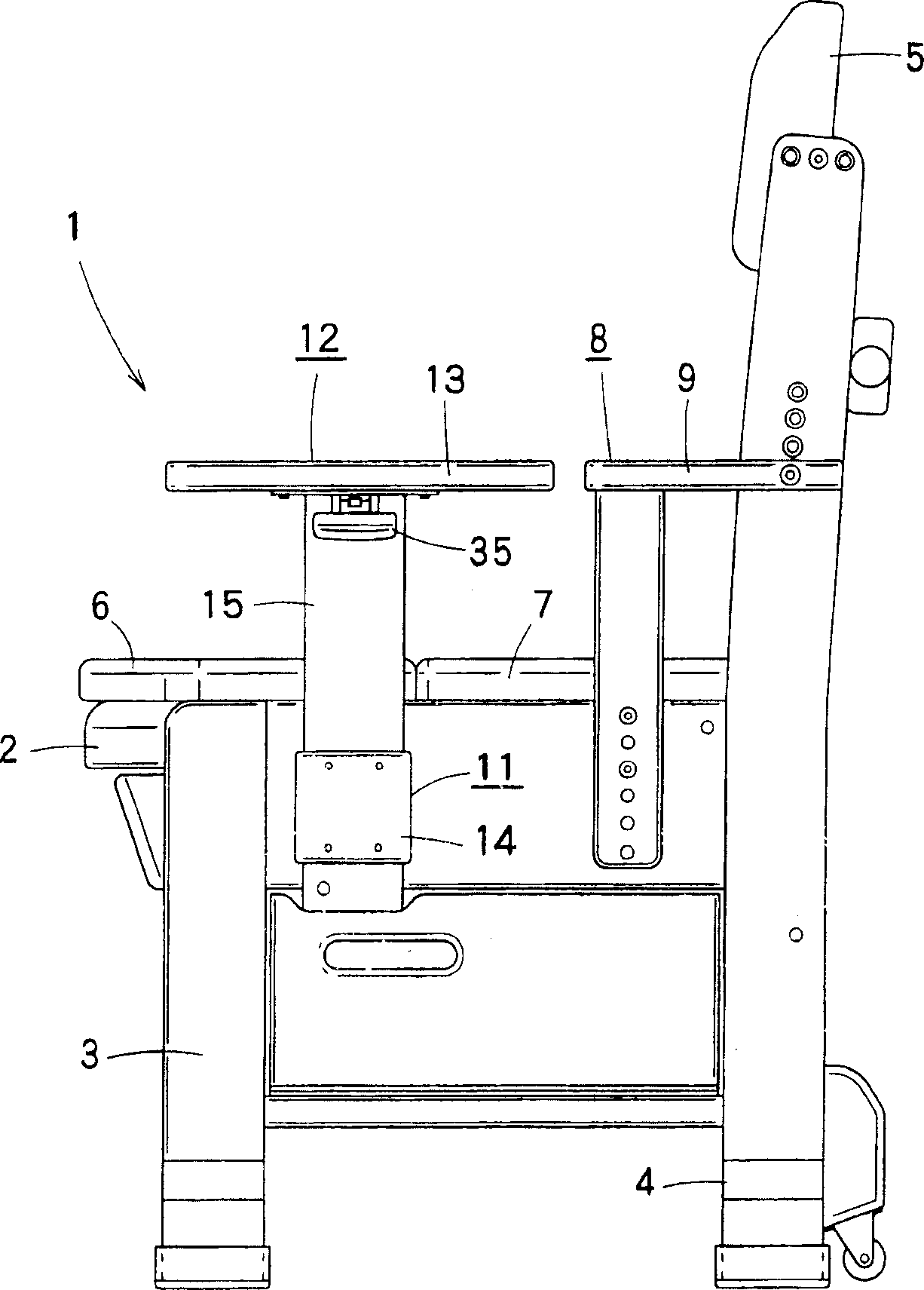
[0036] figure 1 and figure 2 It shows the whole of the chair-type toilet to which the armrest raising and lowering mechanism of the present invention is applied. The chair-type toilet 1 has a chair body 2 composed of two front legs 3, 3 and a rear leg suspended from the chair body 2. 4, 4 supports. Each of the above-mentioned rear legs 4 extends above the above-mentioned chair main body 2 , and a backrest 5 is erected between the two rear legs 4 , 4 .

[0037] A seat plate 6 is detachably provided on the chair main body 2, and a toilet seat, a toilet pot, and the like (not shown) are arranged below the seat plate 6 . In addition, side plates 7 are respectively installed on both sides of the above-mentioned chair main body 2, and on the rear portion of each side plate 7 and each of the above-mentioned corresponding rear legs 4, a fixed armrest 8 can be fixed in a height-adjustable manner, and the fixed armrest 8 It has a fixed armrest main body 9 formed to extend in the hor...


PUM


Abstract

To provide an armrest lifting mechanism of a chair-type toilet capable of safely lifting armrests by a simple operation and being inexpensively manufactured with a simple structure. The armrest lifting mechanism comprises an armrest base part 15 which vertically hangs from each armrest body 13 and which has a plurality of openings 17 formed at intervals in the vertical direction in a side wall 16, a restrained member 23 disposed inside the armrest base part 15 as energized by a spring 34, which can be lifted relative to the armrest base part 15, a stopper 40 whose end is fitted with any one recess 25 of the restrained member 23 via any one opening 17 of the armrest base part 15 and which is energized by a spring 39, and a driving member 35 which relatively moves the restrained member 23 to the armrest base part 15 so that the recess 25 of the restrained member 23 is in a state not to face the opening 17 of the armrest base part 15. An opening 18 for stopping the descent is formed above the uppermost opening 17 of the armrest base part 15, and a recess 26 for stopping the descent and a stopper inhibiting member 29 for storing the armrest base part 15 inside the armrest base part 15 against a spring 28 when relatively descends are formed above the uppermost recess 25 of the restrained member 23.

Description

technical field [0001] The present invention relates to an armrest raising / lowering mechanism of a chair-type toilet having a pair of left and right armrests, and particularly relates to an armrest raising / lowering mechanism of a chair-type toilet capable of easily and safely raising and lowering an armrest. Background technique [0002] The armrests of such chair-type toilets are usually adjustable in height according to the physique of the user. In addition, this chair-type toilet is arranged on the lateral side of the bed, and the user uses it by transferring from the bed to it. It is easy to transfer (for example, refer to Japanese Patent Documents 1, 2, and 3). [0003] [Patent Document 1] Japanese Patent Application Laid-Open No. 9-122041 [0004] [Patent Document 2] Japanese Patent Laid-Open No. 2003-290080 [0005] [Patent Document 3] Japanese Patent Laid-Open No. 2004-97343 [0006] However, in the above-mentioned inventions described in Patent Document 1 and Pa...

Claims


Application Information

Patent Timeline
Patent Type & Authority Applications(China)
IPC IPC(8): A47K17/02A47K17/00
Inventor 井上岳志畑秀夫
Owner COMBI WELLNESS CORPORATION
Why Eureka
Try Eureka