
Device for implementing cursor location using photographic mode

A cursor positioning and cursor technology, which is applied in the directions of measurement devices, user/computer interaction input/output, character and pattern recognition, etc., can solve the problems of reduced use value and inconvenient operation

Inactive Publication Date: 2006-03-29
ZEROPLUS TECH CO LTD
View PDF0 Cites 3 Cited by
  • Summary
  • Abstract
  • Description
  • Claims
  • Application Information

AI Technical Summary

Problems solved by technology

[0008] Since the existing remote control or mouse cannot have the functions of the other party at the same time, when watching digital TV, the user must use the remote control to select the channel and use the mouse to click on the program to watch, thus causing the user to operate the remote control at the same time Use the controller and the mouse to select channels, click on programs or select menus, which will easily cause disadvantages such as reduced use value and inconvenient operation.

Method used


Image

  • Device for implementing cursor location using photographic mode
  • Device for implementing cursor location using photographic mode
  • Device for implementing cursor location using photographic mode

Examples


Embodiment Construction

[0039] In order to achieve the above-mentioned purpose and structure, the technical means adopted by the present invention and their effects, the structure and functions of the embodiments of the present invention will be described in detail as follows in conjunction with the accompanying drawings, so as to facilitate a complete understanding.

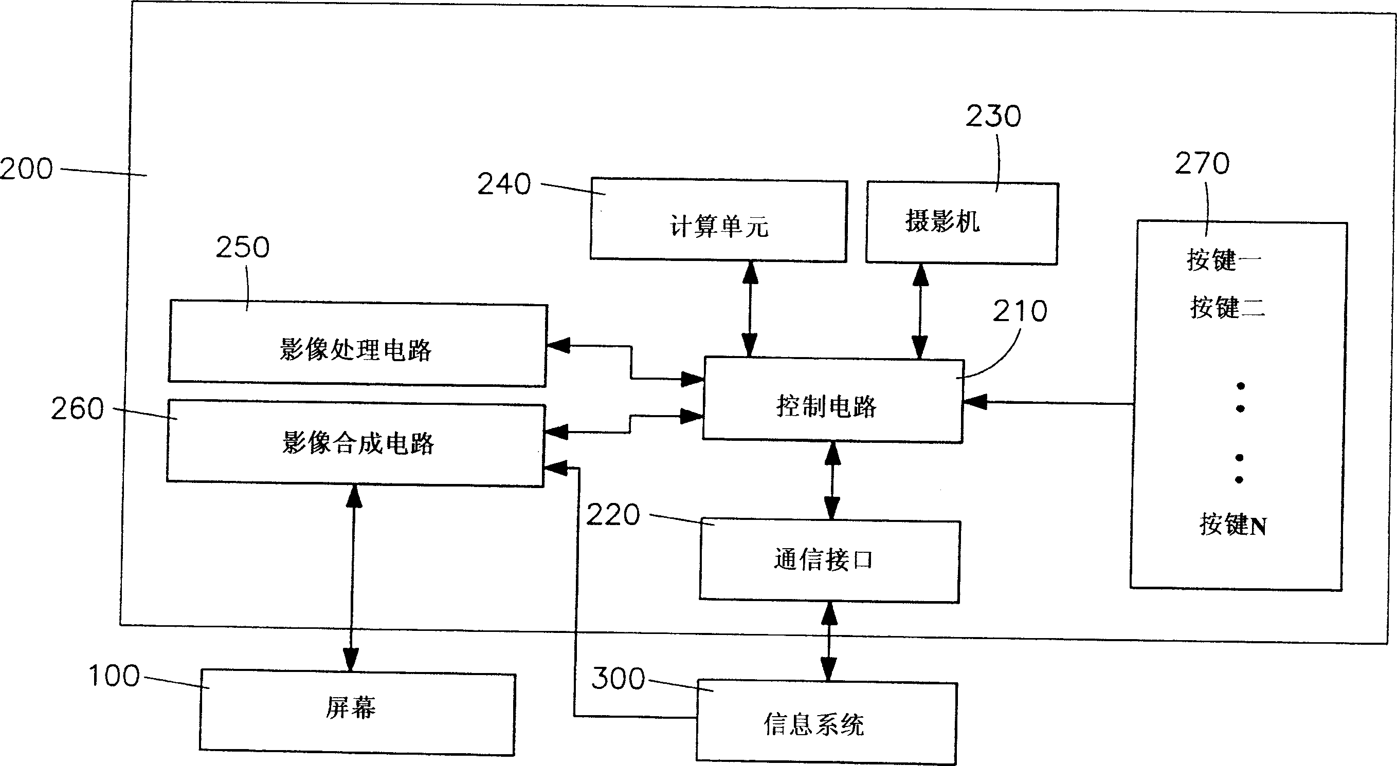
[0040] See first figure 1 Shown is the circuit block diagram of the first embodiment of the photographic cursor device of the present invention. In the first embodiment of the present invention, the photographic cursor device 200 is connected to the information system 300 through the communication interface 220, and the photographic cursor device 200 It includes a control circuit 210, a camera 230, a computing unit 240, an image processing circuit 250, an image synthesis circuit 260 and a plurality of keys 270, wherein the control circuit 210 is electrically connected to these keys 270, and these keys 270 are used to give the user Oper...


PUM


Abstract

A photographic type pointer positioning control device (200)for controlling the positioning of a pointer on a display (100)screen by means of photographing the display screen (100)with a video camera (230)and then processing the video signal thus obtained through an image out-line and recognition processing process and then computing the processed data through a computing unit into (240)a coordinate value corresponding to the aimed point of the video camera (230)at the display screen (100).

Description

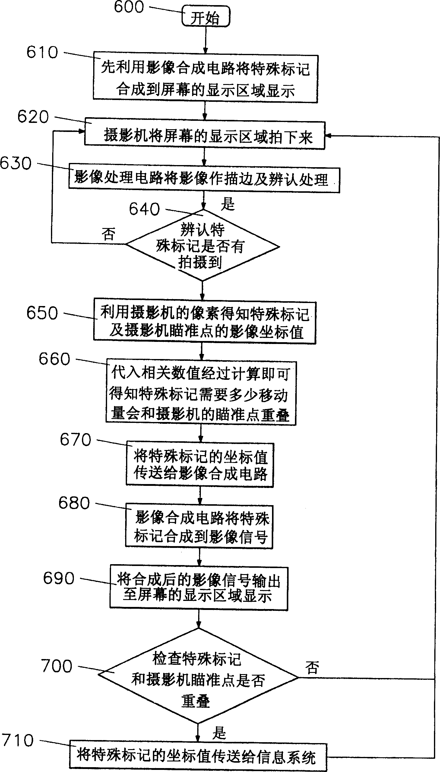
technical field [0001] The present invention relates to a device for cursor positioning by means of photographing, especially a photographic cursor device which uses an image synthesis circuit to synthesize a special mark or cursor into the display area of ​​the screen for display, and draws the image signal captured by the camera as a stroke And identification processing, to obtain the coordinate data of special marks or cursors and camera aiming points or center points, and then output the image signals after image synthesis processing through the image synthesis circuit to the display area of ​​the screen for display, and display the coordinates of special marks or cursors The value is transmitted to the information system to replace the traditional mouse (including optical mouse) and remote control, and allows the user to use the photographic cursor device to control any type of screen without being limited by the type of screen. Background technique [0002] In recent y...

Claims


Application Information

Patent Timeline
IPC IPC(8): G09G5/08G06K9/36G01C9/00G06F15/00G06F3/03G06F3/038
CPCG06F3/0304
Inventor 郑秋豪郑铭国曾俊峰陈崇钦
Owner ZEROPLUS TECH CO LTD
Learn More