Full-function ironing board
An ironing board, full-featured technology, applied in the field of ironing boards, can solve the problems of mental fatigue, physical fatigue, user back pain, etc., and achieve the effects of convenient folding, high integration, and pressure reduction.
- Summary
- Abstract
- Description
- Claims
- Application Information
AI Technical Summary
Problems solved by technology
Method used
Image

Examples
Embodiment 1
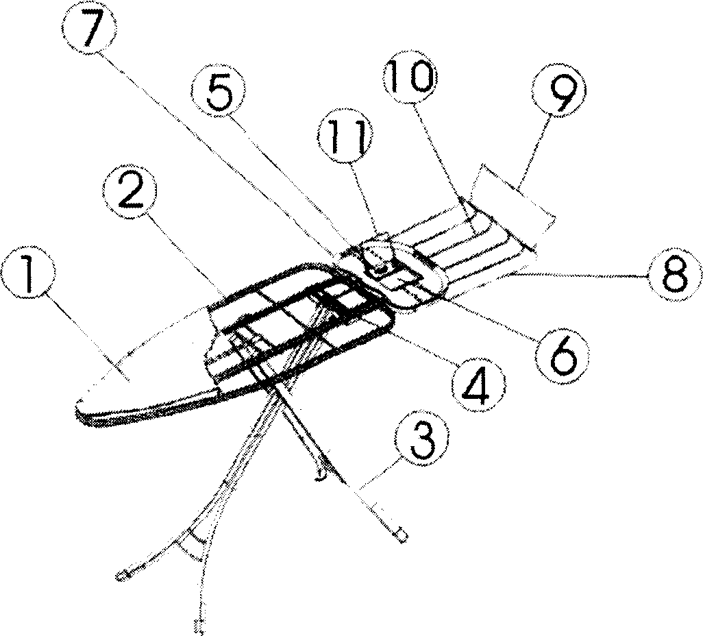
[0018] in figure 1 , figure 2 Among them, the ironing board 1 is used for ironing with the cross supporting legs 3 formed in the prior art to support the panel. The ironing board 1 also includes a hanger 8 with a grid, a frame 2 for supporting the board surface and a tray 7 for supporting the steaming iron. The tray 7 can be made of non-metal fireproof material, or can be made of metal plate material. The tray 7 is movably connected to one side of the ironing board 1 in the longitudinal direction. It can have a frame 18 installed in the middle of the ironing board 1 and can be slid longitudinally along the frame and supported from below. There may be a rectangular hole 6 in the center of the tray 7, and a downwardly inclined curved edge may be formed on the side of the hole. A folding arch 11 movably connected with a hinge is mounted on it, which is used to place the iron in an inclined position of the tray 7. A grid hanger 8 that can extend and retract along the length of the i...
Embodiment 2
[0020] image 3 The structural relationship of the first position of the hanger protruding in the direction of the length of the ironing board 1 is depicted. Figure 4 The structural relationship of the second position extending in the length direction of the ironing board 1 is depicted.
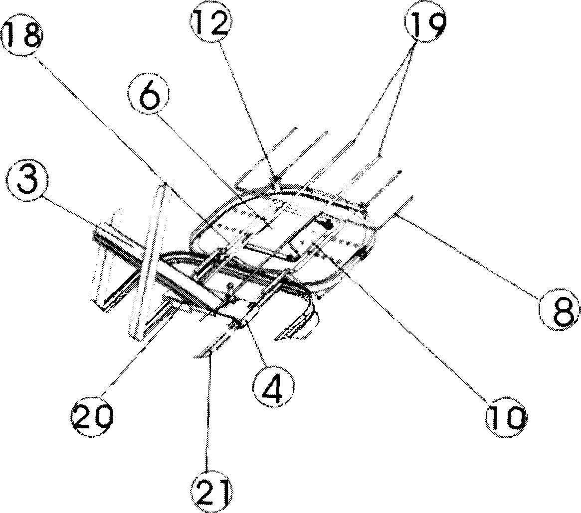
[0021] in image 3 , Figure 4 It can be seen from the detailed perspective view of the second implementation form that they describe the structural form that is basically the same as the basic structure of the first embodiment, and the grid movable connection mechanism is basically the same as that of the first embodiment. The difference is that: In Embodiment 1, the tray 7 for placing the iron is replaced with a J or U-shaped frame 14 that can telescope and slide in the length direction of the ironing board 1, and its two side rods are fixedly connected to the slider holes through the lower part of the ironing board. The short side can be slid to the limiting groove block 15 at the lower part o...
Embodiment 3
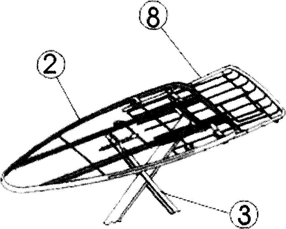
[0023] Figure 5 , Figure 6 , Figure 7 Describes the implementation mode that is further improved and developed on the basis of the second embodiment. In the perspective view of the third implementation form shown in Figure 6, the frame basket of the grid hanger 8 is strengthened, and the J-frame 14 structure of the second embodiment is omitted to make it more concise and make it form a Frame the basket for easy placement Figure 7 The plate cover 17 shown. The plate cover 17 can be a non-metallic heat-resistant material or a metal material. Figure 6 A perspective view of this embodiment viewed from under the ironing board 1 is described. Figure 8 is a top perspective view of the present invention and an exploded view of the attachments to facilitate seeing its concise form.
[0024] The tray panel of the present invention can be embossed to reduce the heat transfer of the iron.
PUM
 Abstract
Description
Claims
Application Information
 - R&D
- Intellectual Property
- Life Sciences
- Materials
- Tech Scout
- Unparalleled Data Quality
- Higher Quality Content
- 60% Fewer Hallucinations
Browse by: Latest US Patents, China's latest patents, Technical Efficacy Thesaurus, Application Domain, Technology Topic, Popular Technical Reports.
© 2025 PatSnap. All rights reserved.Legal|Privacy policy|Modern Slavery Act Transparency Statement|Sitemap|About US| Contact US: help@patsnap.com