Electromechanical trigger and an electronical safety appliance with the same

A trip device, electromagnetic technology, applied in electromagnetic protection switches, switches with electric heat and electromagnetic release, electrical components, etc., can solve problems such as reducing the reliability of relays

Active Publication Date: 2010-04-14
SCHNEIDER ELECTRIC IND SAS
View PDF5 Cites 16 Cited by
  • Summary
  • Abstract
  • Description
  • Claims
  • Application Information

AI Technical Summary

Problems solved by technology

[0005] In order for the pins to be within an area that allows the relay to operate optimally, the mentioned components must comply with a large number of dimensional tolerances, which reduces the reliability of the relay

Method used


Image

  • Electromechanical trigger and an electronical safety appliance with the same
  • Electromechanical trigger and an electronical safety appliance with the same
  • Electromechanical trigger and an electronical safety appliance with the same

Examples


Embodiment Construction

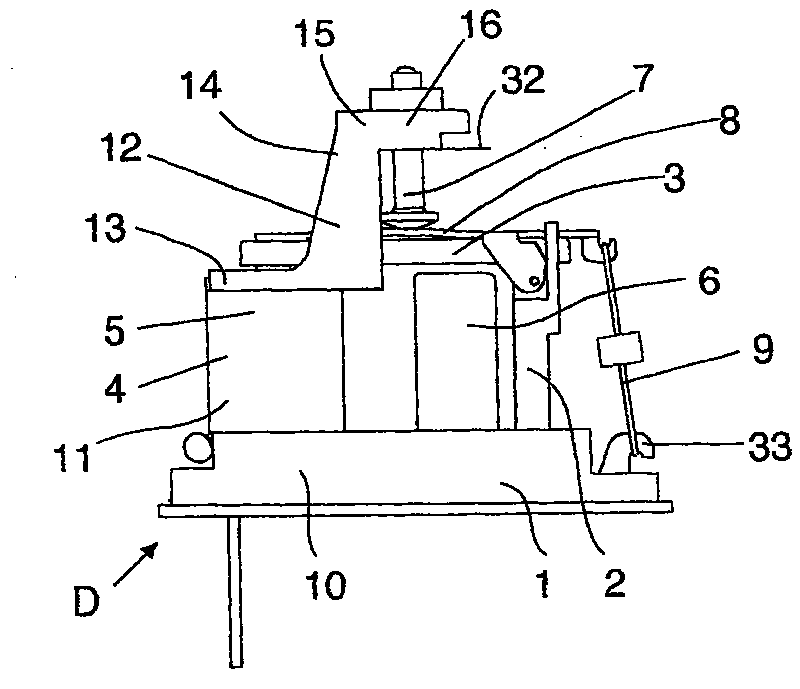
[0035] figure 1 , it can be seen that the electromagnetic tripping device D comprises, in a manner known per se, a bracket 1 supporting a U-shaped armature 2, the two ends of which form two polarized surfaces with respect to said armature 2 Pivoting vanes 3 co-operate, said vanes 3 being able to move over said polar surfaces to close the magnetic circuit formed by the armature 2 and the vanes 3 . This trip device D also comprises a trip coil 4 , mounted around a casing 5 surrounding the magnetic circuit, said coil being able to react against the force of the magnet 6 in order to move the vane 3 . This tripping device D also includes the reset pin 7 of the blade 3, which is used to act on the plate 8 fixed on the blade 3 and to damp the impact of the reset force. The function of the tripping device of the mechanism of the equipment; and the return spring 9 of the blade 3.

[0036] The operation of such a trip device D will be described later. At rest, with no current in the ...


PUM


Abstract

The present invention provides an electromagnetic tripping device. The device has a cradle (1) supporting a U-shaped armature (2) whose ends form polar surfaces cooperating with a palette (3). The palette is brought on the surfaces to close a magnetic circuit formed by the armature and the palette. A trip coil (4) is mounted around a yoke frame surrounding the magnetic circuit and can thwart the force of a magnet to move the palette. A resetting top cap (7) of the palette is mounted slidingly in a support (12) included in the cradle. The palette (3) pivots with respect to the U-shaped armature. The feature of the electromagnetic tripping device is that the cradle (1) includes the said top cap (7) and support (12).

Description

technical field [0001] The present invention relates to an electromagnetic tripping device comprising a bracket supporting a U-shaped armature with two polarized surfaces formed at both ends of the armature cooperating with vanes pivoting relative to said armature, said The vanes are movable onto said polarized surfaces to close the magnetic circuit formed by the armature and the vanes; As for the leaf plate, the tripping device also includes a reset pin of the leaf plate, and the reset pin is slidably installed on a support. Background technique [0002] Currently, the relay pin is mechanically and functionally connected to the blade of the relay by means of several components, namely the housing, the mounting plate, the armature, the coil casing or the hinge. [0003] Various tripping devices of the aforementioned type are known, such as those described in patents EP 0829895, EP 0786789, EP 0643410 and EP 4110660, in which the pin support is a box. [0004] All of these ...

Claims


Application Information

Patent Timeline
Patent Type & Authority Patents(China)
IPC IPC(8): H01H71/24H01H73/36H01H73/48H01H75/10H01H75/12H01H77/06H01H81/04H01H71/32H01H71/58
CPCH01H71/326H01H71/323
Inventor 内丁·塞雷诺奥德丽·奥利维尔阿兰·卡齐夫斯基
Owner SCHNEIDER ELECTRIC IND SAS
Why Eureka
Try Eureka