Vortex air outlet device

A technology of tuyere device and air outlet, which is applied in the field of air outlet device, which can solve the problems of increasing the guiding degree of the blade body, increasing the cost, complicated mechanism, etc., and achieve the effect of increasing the diffusion range, improving the effect and reducing the cost

Inactive Publication Date: 2006-05-03
KUKEN INDS +1
View PDF0 Cites 12 Cited by
  • Summary
  • Abstract
  • Description
  • Claims
  • Application Information

AI Technical Summary

Problems solved by technology

[0005] The existing swirl air outlet device is constituted as described above, although the position adjustment of the movable vane part 103 is adjusted to change the state in which the conditioned air is discharged as a swirl flow, but the position of each vane body of the fixed vane part 102 and the movable vane part 103 The angle of inclination is always fixed, and the airflow cannot be reliably guided in the desired direction only by adjusting the position of the movable vane part 103
In particular, for the velocity component in the horizontal direction of the airflow, not only the degree of guidance of the blade body is increased and the rotational velocity component is strengthened, but also the Coanda effect caused by the shape of the surface part 104 is used to the maximum extent, and the direction of the airflow is directed toward the horizontal direction. Therefore, it is easy to be affected by the surrounding environment of the air outlet.

Method used


Image

  • Vortex air outlet device
  • Vortex air outlet device
  • Vortex air outlet device

Examples


Embodiment Construction

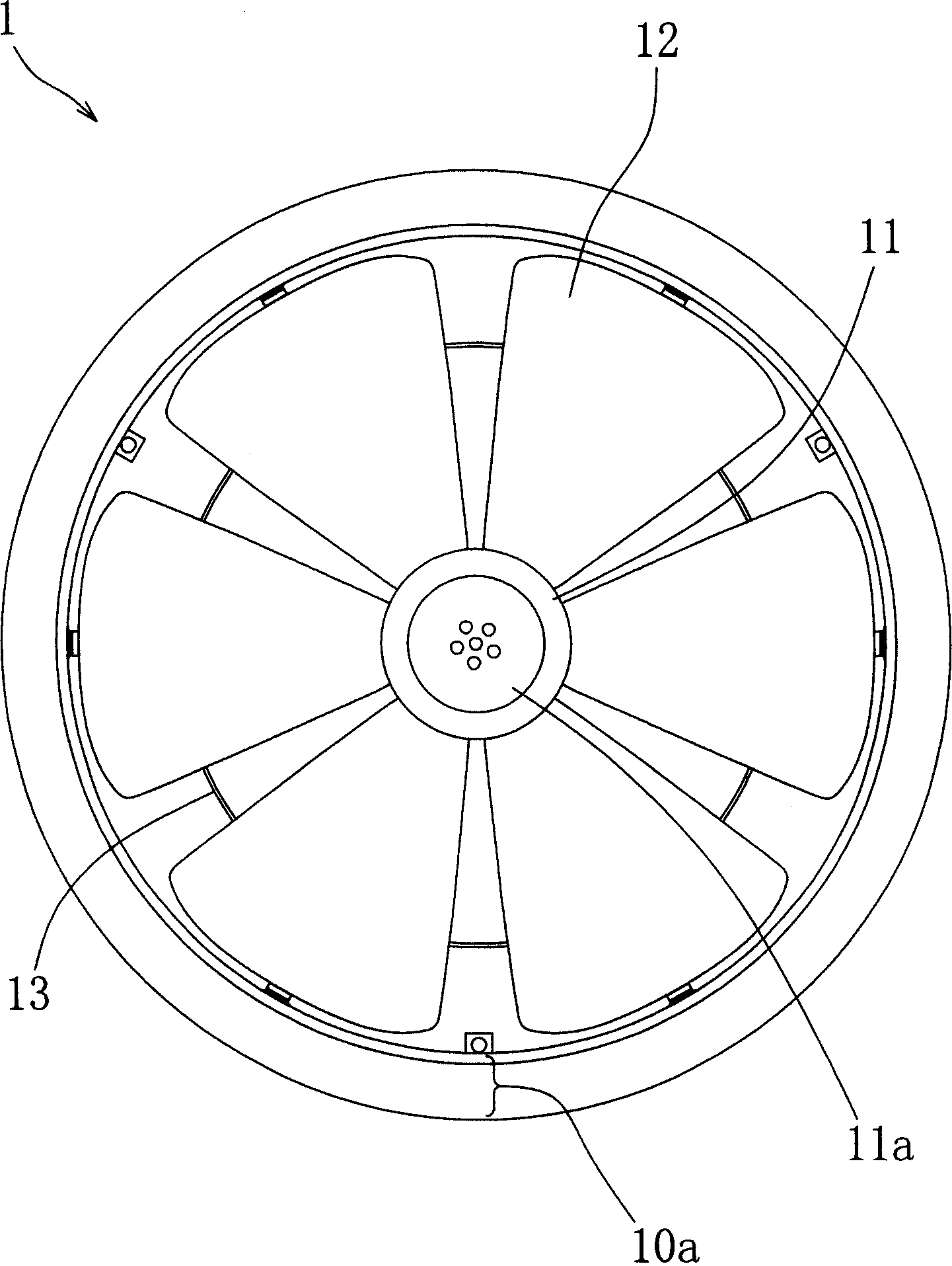
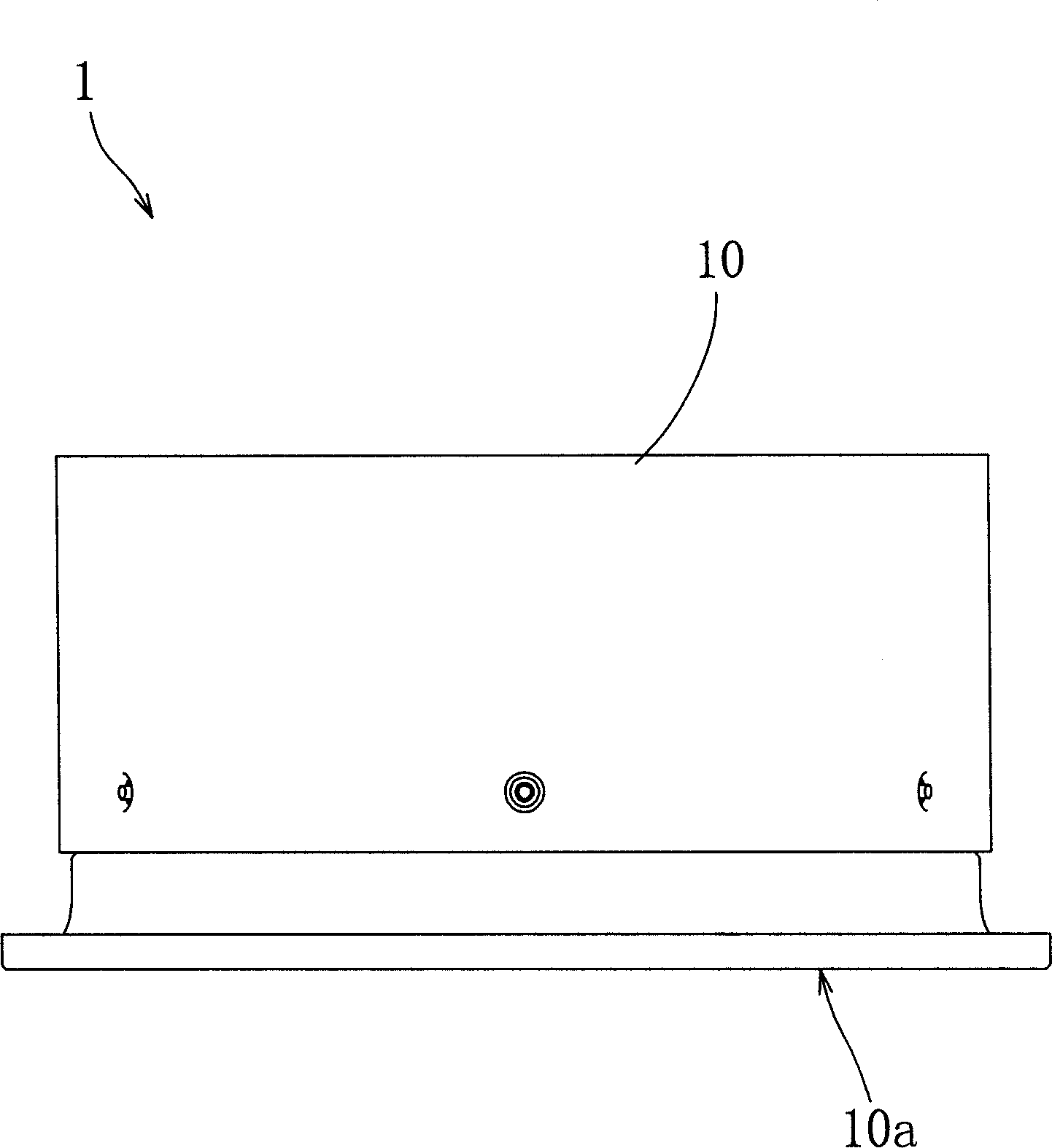
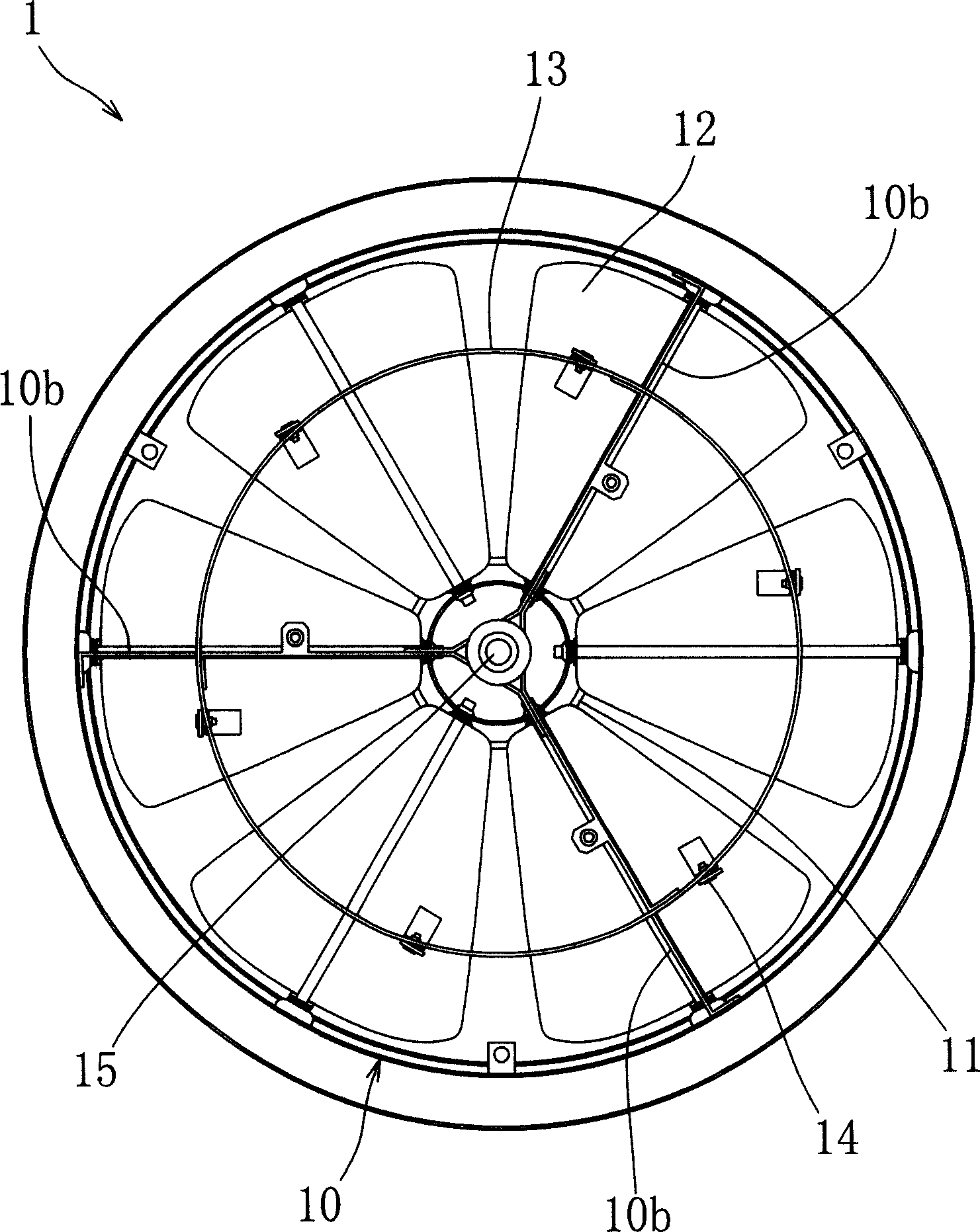
[0034] Below, based on Figure 1 to Figure 5 , illustrating the swirl air outlet device related to one embodiment of the present invention. figure 1 It is a bottom view of the swirl air outlet device related to this embodiment, figure 2 It is a right side view of the swirl air outlet device related to this embodiment, image 3 It is a top view of the swirl air outlet device related to this embodiment, Figure 4 It is an explanatory diagram of the horizontal discharge state and the vertical discharge state in the swirl air outlet device related to this embodiment, Figure 5 It is an explanatory diagram of the inclination state of the blade body in the horizontal discharge state and the vertical discharge state in the swirl air outlet device related to the present embodiment.

[0035] In each of the above-mentioned figures, the swirl air outlet device 1 related to the present embodiment has a structure including a substantially cylindrical air outlet main body 10, and one f...


PUM


Abstract

The invention discloses a cyclone air outlet device, which is characterized by the following: placing multiple blades in the opening region of air outlet host to do free inclining movement around radiation shape axis; adjusting the inclined angle of each blade through the driving device movement; changing flow direction through blade; controlling the interflow of each blade as cyclone state; strengthening the vertical downward speed component of flow through increasing the inclined angle of blade; strengthening transverse speed component through decreasing the inclined angle of blade; selecting the discharging state ranged from vertical direction to transverse direction corresponding to each air adjustment condition.

Description

technical field [0001] The present invention relates to an air outlet device arranged facing a space to be air-conditioned, especially a swirling air outlet device that can properly adjust the swirling discharge state of airflow by simply controlling the inclination angle of the vane plate. Background technique [0002] In air-conditioning equipment, the air outlet device that discharges the conditioned air sent through the duct to the indoor space that is the space to be air-conditioned is generally used as a device that makes the air flow of the conditioned air flow straight in one or more directions. , In addition, there is also a device that makes the direction of a plurality of exhaust airflows coincide with the tangential direction of a circle, and generates a rotational velocity component by the confluence of each airflow, and discharges it as a swirling flow. This mechanism for discharging conditioned air as a swirling flow is configured by setting leaf-shaped valves...

Claims


Application Information

Patent Timeline
IPC IPC(8): F24F13/065
Inventor 中岛洋一宋以钊
Owner KUKEN INDS
Why Eureka
Try Eureka