Smoke screen generator
A technology for generating devices and smoke screens, which is applied in the direction of smoke/gas/colored/smell powder alarms, etc., which can solve the problems of time required to block the field of view, unfavorable smoke diffusion, and time required
- Summary
- Abstract
- Description
- Claims
- Application Information
AI Technical Summary
Problems solved by technology
Method used
Image

Examples
no. 1 approach
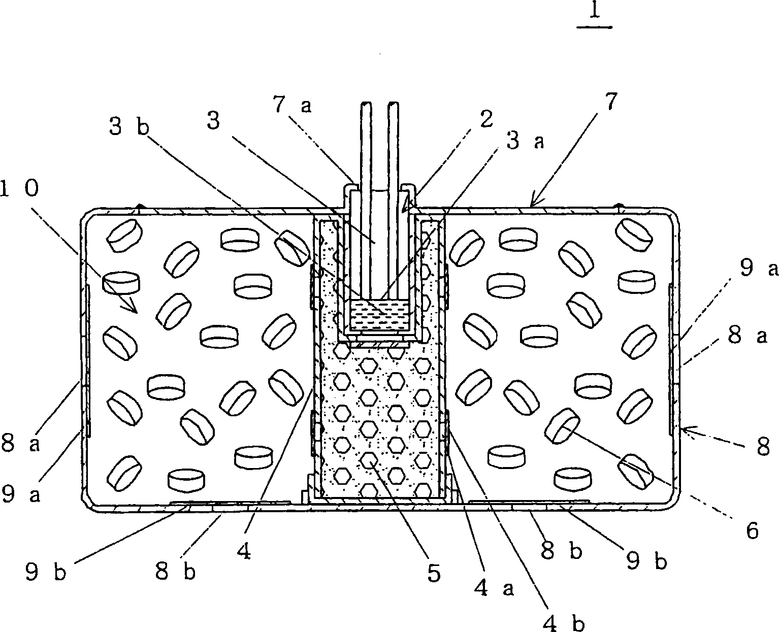
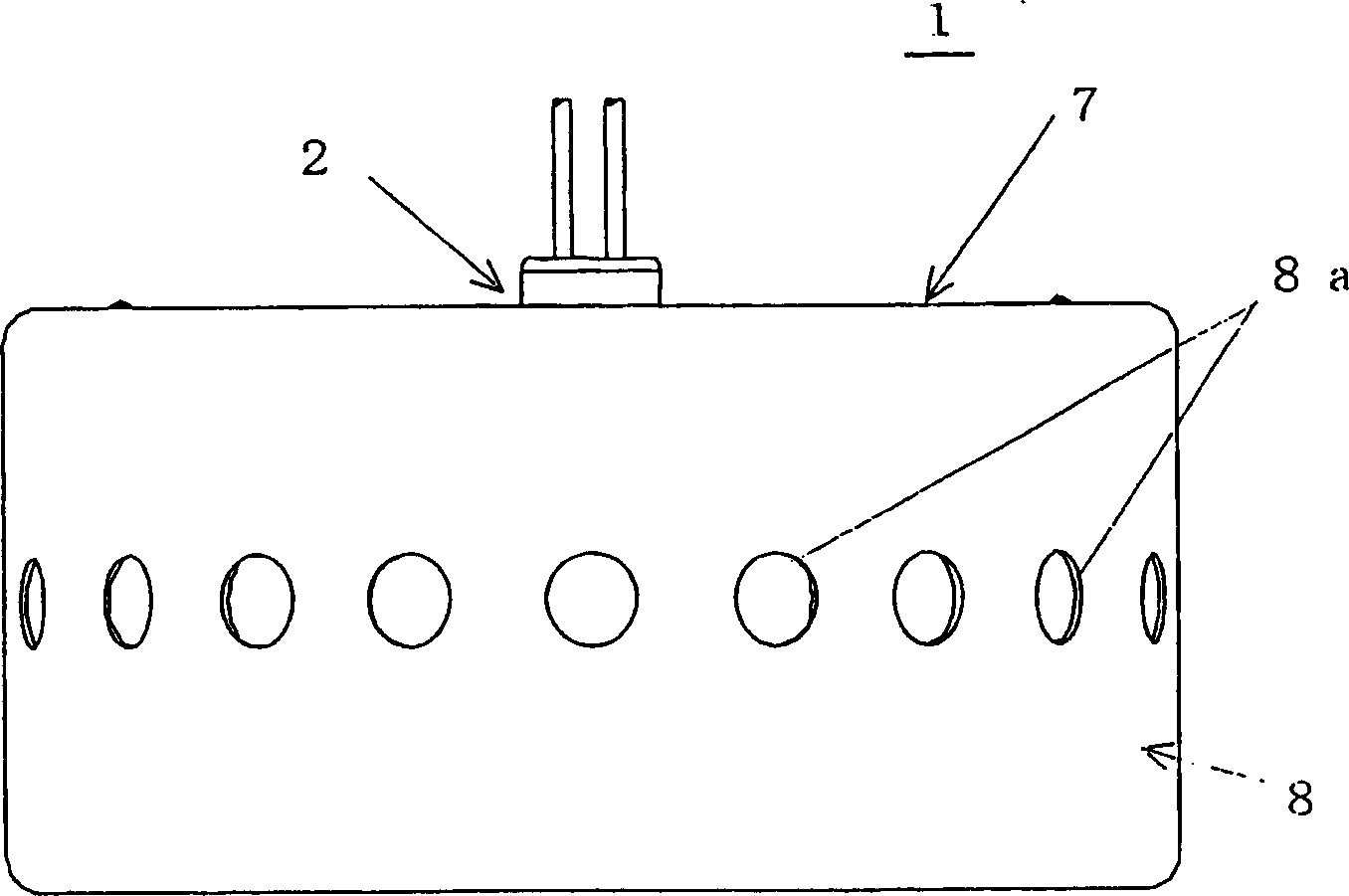
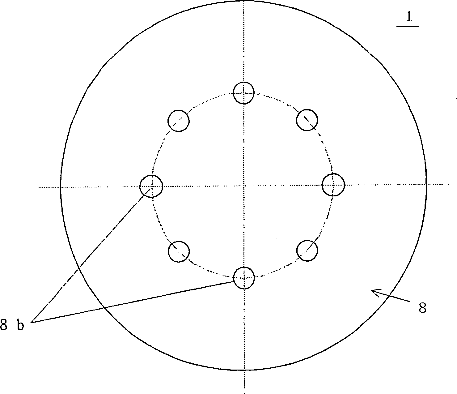
[0067] Figure 1 to Figure 3 , represents the smoke generating device 1 according to the first embodiment of the present invention.
[0068] The smoke generating device 1 of this embodiment includes: an ignition device 2 ; an aerosol 6 that is combusted by the ignition device 2 to generate smoke; and a combustion chamber 10 that accommodates the aerosol 6 .
[0069] The ignition device 2 includes: an igniter 3; an igniter case 4 surrounding the igniter 3; and an igniter 5 filled in the igniter case 4 to increase energy from the igniter 3 and spread combustion to the aerosol 6; And it is installed in the central part of the combustion chamber 10 to spread the combustion from the ignition powder 5 to the aerosol 6 evenly.
[0070] The igniter 3 has a heating element 3 a that generates heat by energization, and an ignition powder 3 b that is ignited by the heating element 3 a. Here, astringent was used as the ignition powder. The igniter 3 is engaged with the cap 7 and placed ...
no. 2 approach
[0100] Figure 4 to Figure 6 A smoke screen generating device 20 according to a second embodiment of the present invention is shown.
[0101] The smoke generating device 20 of this embodiment includes: an ignition device 22; an aerosol 26 that generates smoke by burning the ignition device 22; a combustion chamber 30 that accommodates the aerosol 26; and a spray chamber 31 that is adjacent to the combustion chamber 30 .
[0102] The difference between the smoke generating device 20 of the present embodiment and the smoke generating device 1 of the first embodiment is that an ejection chamber 31 is provided adjacent to the combustion chamber 30, and the gas smoke is not released from the combustion chamber 30, but is emitted from the ejection chamber. 31 released.
[0103] The bottomed chamber 28 made of stainless steel with a thickness of about 1.5mm constituting the combustion chamber 30 is provided with a bottomed covering portion 28b in order to form the discharge chamber...
experiment example 1
[0137] Such as Figure 7 As shown, at a width of about 5.3m x a depth of about 2.1m x a height of about 2.3m (about 26m 3 ) in the center of the room 50, at a position 30 cm from the top side, the smoke generating device 20 of this embodiment is installed.
[0138] In addition, the number of the first smoke outlet 32a and the second smoke outlet 32b of the device in Experimental Example 1 is 20 and 8, respectively. At this time, a sound pressure measurement sensor 51 is provided for measuring the sound pressure level.
[0139] Next, energize the igniter and operate the device by remote operation.
[0140] As a result, the combustion of the aerosol ends in about 0.5 seconds, and within about 1 to 2 seconds from the start of the aerosol combustion, the smoke is ejected from the first smoke outlet 32a and the second smoke outlet 32b. The relationship between time and combustion chamber pressure is as follows Figure 8 As shown, the pressure in the combustion chamber becomes t...
PUM
 Abstract
Description
Claims
Application Information
 - R&D Engineer
- R&D Manager
- IP Professional
- Industry Leading Data Capabilities
- Powerful AI technology
- Patent DNA Extraction
Browse by: Latest US Patents, China's latest patents, Technical Efficacy Thesaurus, Application Domain, Technology Topic.
© 2024 PatSnap. All rights reserved.Legal|Privacy policy|Modern Slavery Act Transparency Statement|Sitemap