Lens cone driving device, and lens driving module and camera module

A driving device and camera module technology, applied in the direction of electromechanical devices, installation, optics, etc., can solve the problems of not getting the degree of freedom of the stepping motor, not being able to eliminate the configuration of the rotor on the cylindrical stator, and not being able to get the degree of freedom, etc.

A driving device and camera module technology, applied in the direction of electromechanical devices, installation, optics, etc., can solve the problems of not getting the degree of freedom of the stepping motor, not being able to eliminate the configuration of the rotor on the cylindrical stator, and not being able to get the degree of freedom, etc.

CN1773320AInactive Publication Date: 2006-05-17SEIKO INSTR INC

Image

  • Lens cone driving device, and lens driving module and camera module
  • Lens cone driving device, and lens driving module and camera module
  • Lens cone driving device, and lens driving module and camera module

Examples


Embodiment Construction

[0055] refer to Figure 1 to Figure 8 One embodiment of the present invention will be described.

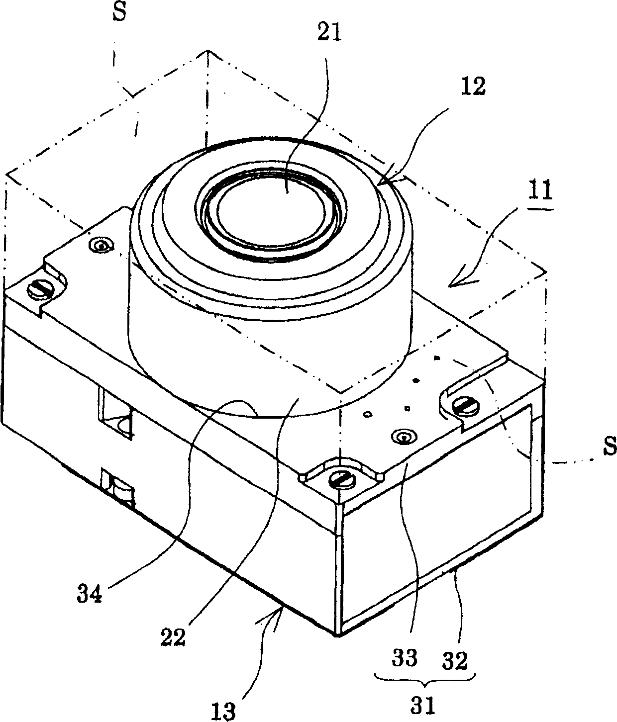
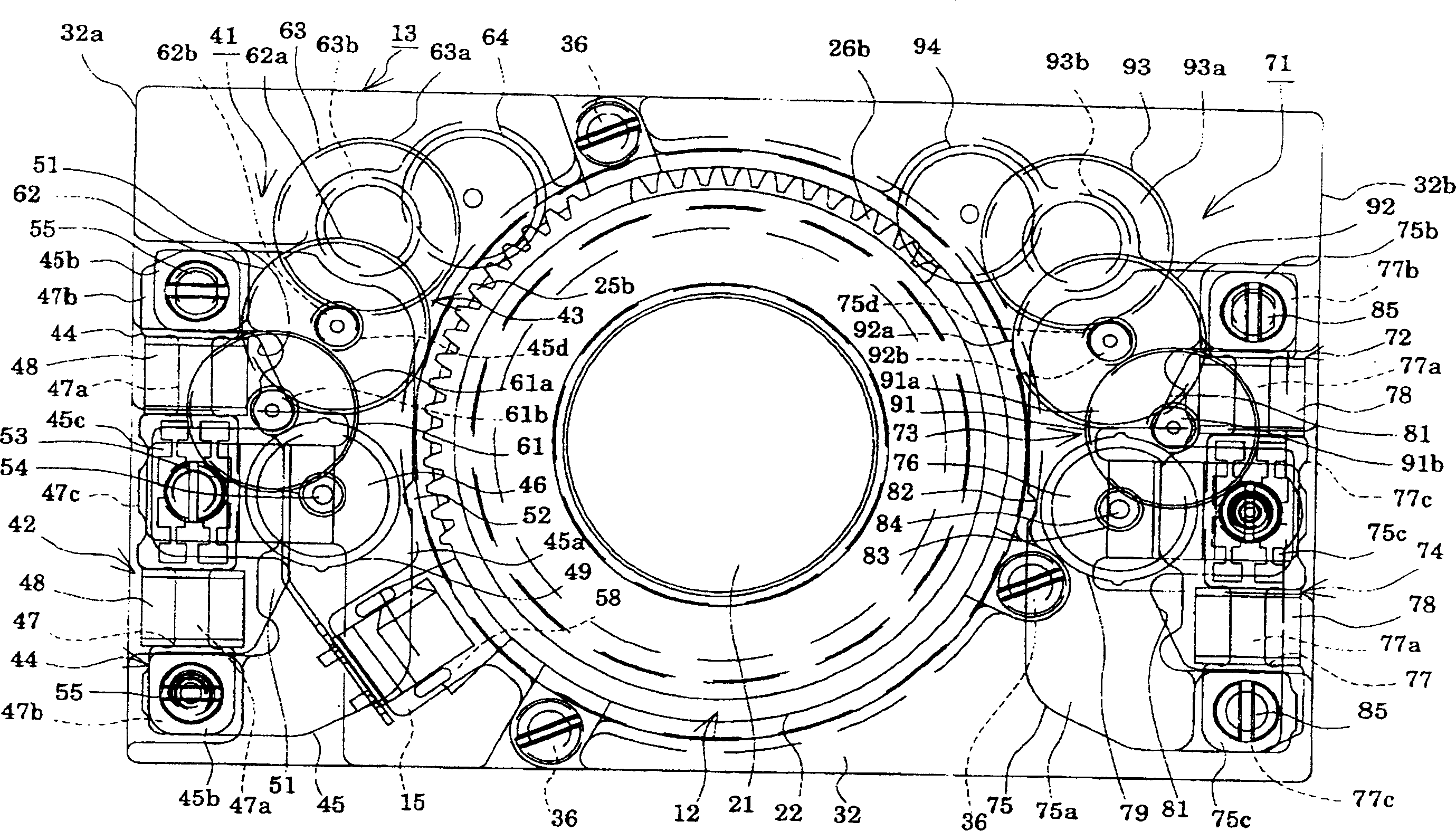
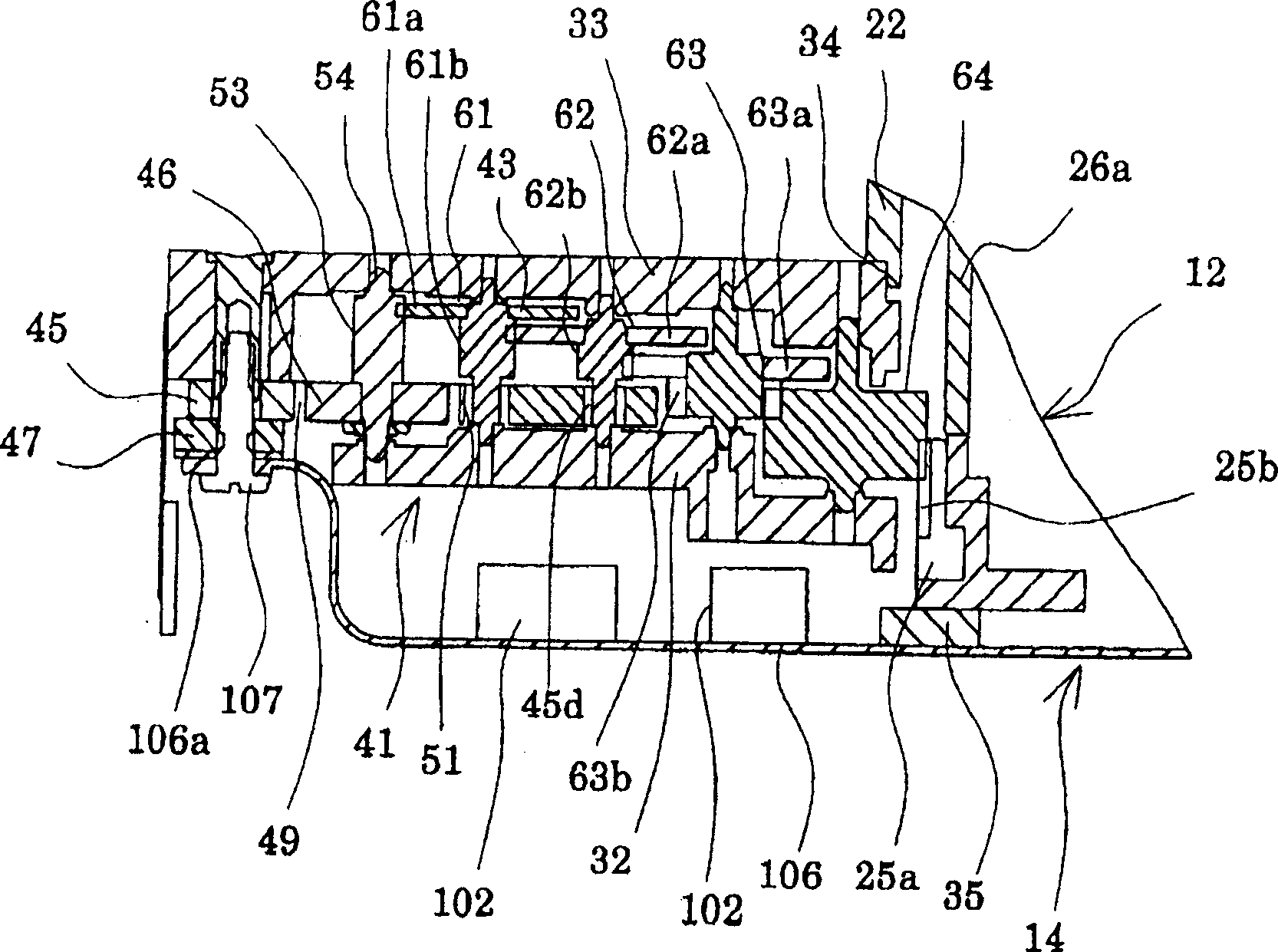
[0056] figure 1 and Figure 7 Reference numeral 11 in denotes a camera module. The camera module 11 is mounted on a printed wiring board in a body of a thin portable electronic device such as a card-shaped digital camera or a mobile phone with a camera function. The camera module 11 includes a lens barrel 12 , a lens barrel drive device 13 , a circuit component 14 , a sensor 15 constituting a detection unit, and an imaging element 16 .

[0057] Lens barrel 12, in figure 1 and figure 2 In the outer casing 22 shown to support the fixed lens 21, there are respectively built-in Figure 7 Focusing lens 23 and zoom lens 24 are shown, and, having Figure 7 The lens drive mechanism 25, 26 is shown. A lens drive mechanism 25, bears the first lens function such as focusing function together with the focus lens 23, has the rotatable focus ring 25a of lens barrel 12 prescribed ang...


PUM


Abstract

The present invention provides a camera module capable of securing a space around a lens barrel and suppressing magnetic interference between adjacent stepping motors. A focus actuator (41) and a focus actuator (71) for actuating the lens barrel (12) are installed on one side of the base (32) on which the lens barrel (12) capable of focusing and zooming is installed. Each actuator (41, 71) is provided with a stepping motor (42, 72) and a reduction gear train (transmission mechanism) (43, 73) for linking the lens barrel (12) with the motor. The height of each actuator (41, 71) is configured to be lower than the height of the lens barrel (12) based on the above-mentioned one surface. These actuators (41, 71) are deployed along one surface of the base (32) so as to be separated in the circumferential direction of the lens barrel (12).

Description

technical field [0001] The present invention relates to a lens barrel driving device used for focusing or zooming of the lens barrel mounted on portable electronic equipment such as a card-shaped digital camera or a mobile phone with a camera, etc., and a camera module (camera module) comprising the device. . [0002] In addition, the present invention relates to a lens driving module used for focusing and zooming of a lens group mounted on a portable electronic device such as a digital card camera or a mobile phone with a camera, and a camera module including the lens driving module. Background technique [0003] In the prior art, there are known lens barrels and cameras configured as follows: it has a plurality of actuators for performing the focus function, zoom function, and aperture function of the lens barrel, and by arranging these actuators along the Viewing from the direction of the optical axis of the lens barrel to the direction of the two surfaces forming the co...

Claims


Application Information

Patent Timeline
17 May 2006
Publication
CN1773320A
IPC
G02B7/02; H02K33/18
Inventors
小棚木进; 久米章