
Air-conditioner for vehicles

Inactive Publication Date: 2005-05-05
DENSO CORP
View PDF3 Cites 23 Cited by
  • Summary
  • Abstract
  • Description
  • Claims
  • Application Information

AI Technical Summary

Benefits of technology

[0006] The present invention has a first object to provide an air conditioner for vehicles in which air streams are formed so that hot air blown out from blow-out ports is prevented from being blown to the upper bodies of occupants and thus amenity under heating operation is not damaged.
[0007] Furthermore, the invention has a second object to provide an air conditioner for vehicles which can secure a head portion space by constructing an air conditioning unit so that no blow-out duct is disposed at the ceiling portion of the vehicle.
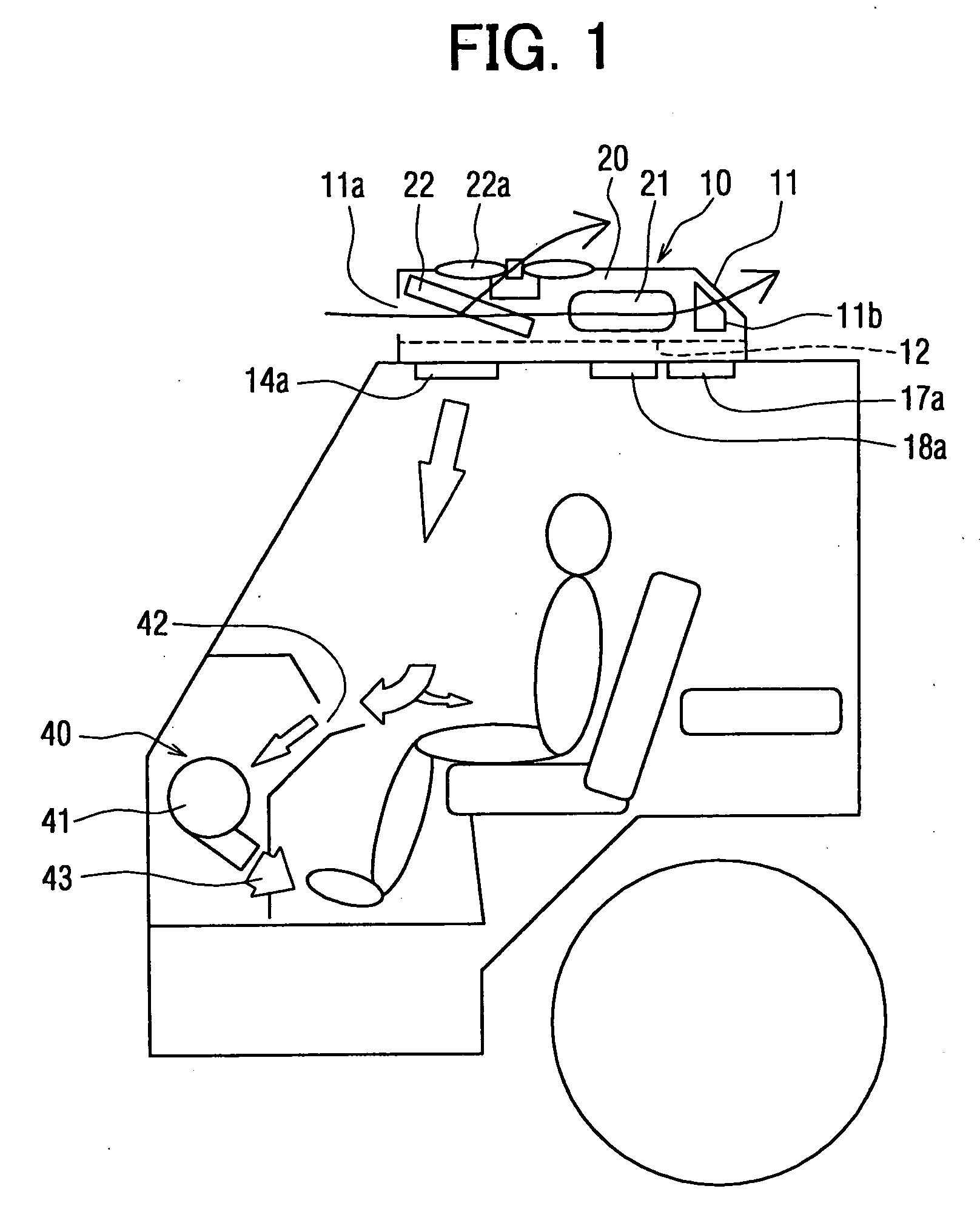
[0008] The invention has an air blowing unit which can suck hot air blown out from the air conditioning unit provided at the ceiling portion of the vehicle to the lower side of the cabin of the vehicle and blow out the hot air thus sucked to the feet of occupants. Accordingly, the blow-out of the hot air to the upper bodies of the occupants can be suppressed at maximum, and also amenity under heating operation can be prevented from being damaged because the hot air is blown to the feet of the occupants. Furthermore, blow-out ports for heating may be provided between the front window at the front side of the vehicle and the occupants without providing the blow-out ports at the front side of the vehicle, and thus it is easy to mount the blow-out ports for heating.

Problems solved by technology

However, when hot air is blown out to the upper bodies of the occupants to carry out heating operation, the amenity for the occupants is damaged.
As compared with the compact special kind vehicle as described above, a truck type vehicle is designed so that the front side of the roof and ceiling portions of the vehicle are streamlined in shape as a whole in order to enhance the traveling performance of the vehicle, and thus it is more difficult to form a space in which the blow-out ports and the air blow-out ducts are disposed at these portions.

Method used


Image

  • Air-conditioner for vehicles
  • Air-conditioner for vehicles
  • Air-conditioner for vehicles

Examples


first embodiment

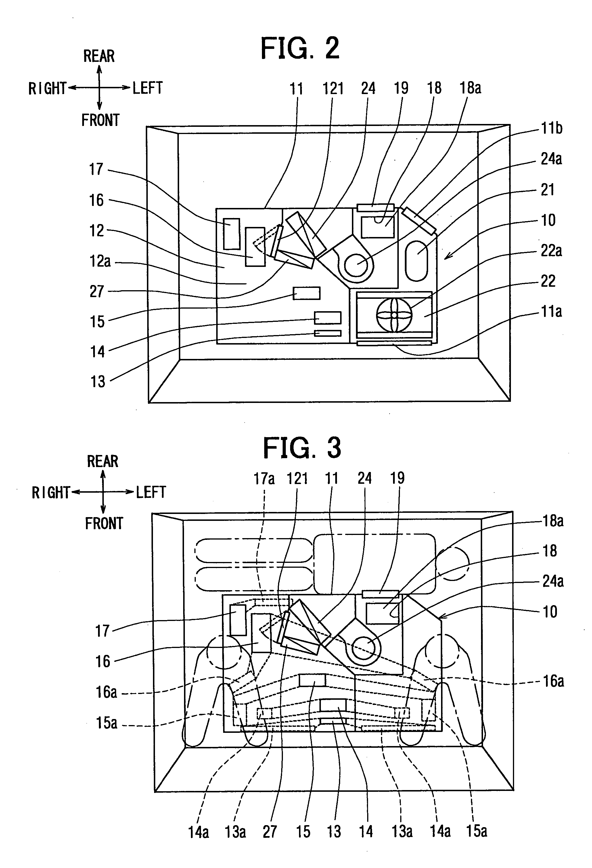
[0015] As shown in FIGS. 1 to 3, an air conditioner for vehicles according to this embodiment comprises an air conditioning unit 10 mounted at the roof portion of a vehicle, plural blow-out ports 13a to 17a disposed at the ceiling portion of the vehicle, a suction port 18a for sucking air in the cabin of the vehicle and an air blowing unit 40 disposed in a dashboard of the vehicle. The air conditioning unit 10 is an unit for sucking air in the cabin of the vehicle from an air suction port 18a and blowing out air-conditioned air adjusted in temperature to plural blow-out ports 13a to 17a, and the inside of an air conditioning case 11 thereof is partitioned into upper and lower stages by a partitioning member 12. At the upper stage, a refrigerating cycle apparatus 20 containing a compressor 21, a condenser 22, etc. is integrally disposed, and plural blow-out opening portions 13 to 17 for opening air flow passages in accordance each blow-out mode are formed. At the lower stage are form...

second embodiment

[0054] In the first embodiment, the air blowing unit 40 is disposed in the dashboard at the front side of the vehicle. However, it may be disposed in a door trim of the vehicle. Specifically, as shown in FIG. 5, air blowing units 40a are disposed in the right and left door trims of the vehicle. The suction port 42 at the upper end is provided within the blow-out range of the air-conditioned air blown out from the side defroster blow-out port 15a, and the blow-out port 43 at the lower end is designed to blow out air to the foot of an occupant. The air blower 41 is electrically connected to the controller 30 so that in the case of the blow-out mode in which the side defroster opening portion 15 is opened, the air blower 41 is controlled interlockingly.

[0055] Accordingly, as in the case of the first embodiment, hot air from the side defroster blow-out ports 15a is sucked and then blown out to the foot side, so that amenity under heating operation is not damaged. Furthermore, the air b...

third embodiment

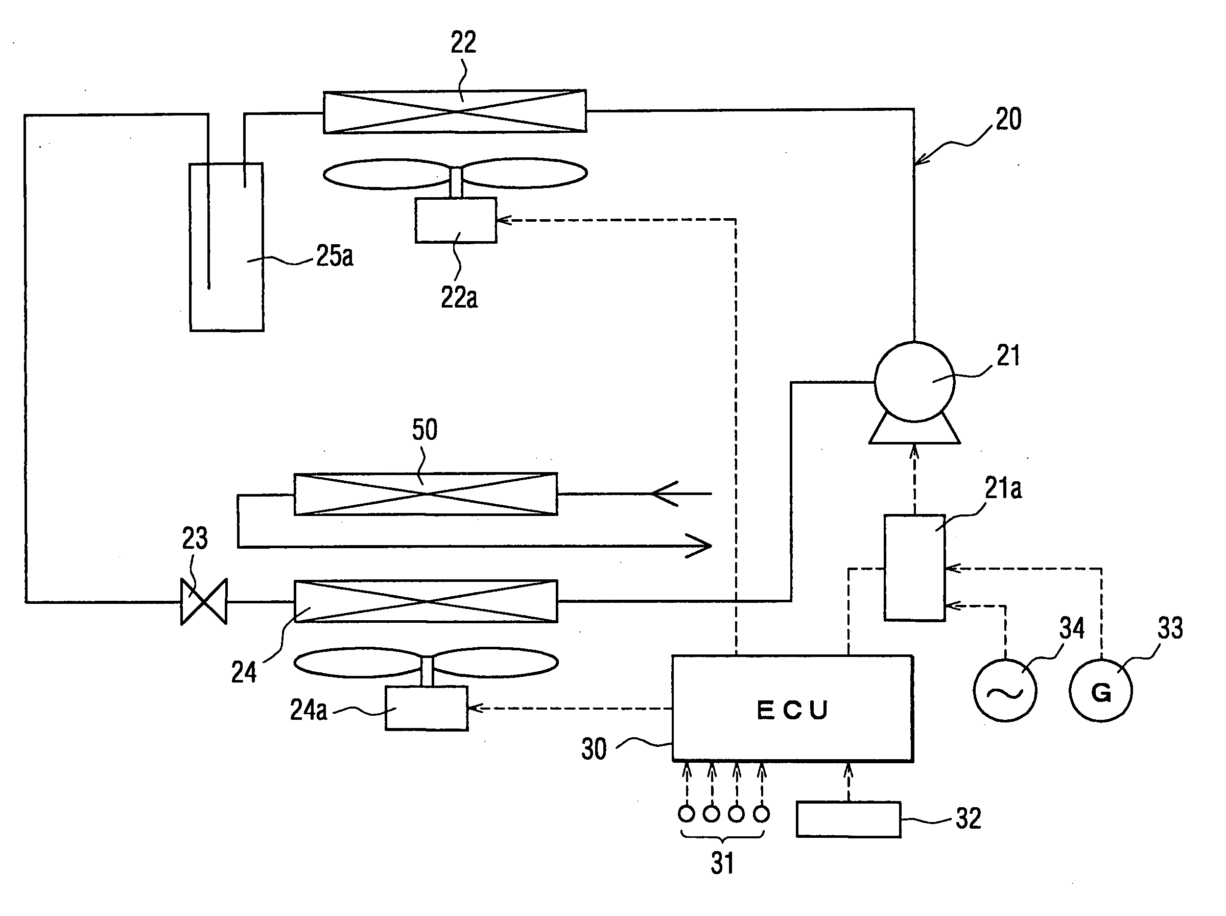
[0056] In the above embodiments, the refrigerating cycle apparatus 20 accommodated in the air conditioning unit 10 is constructed as the heat pump cycle in which the refrigerant flow direction is switched between the cooling operation and the heating operation. However, as shown in FIG. 6, it may be an apparatus for carrying out cooling operation and heating operation by combining a refrigerating cycle apparatus 20 for carrying out only the cooling operation with a heater core 50 serving as a heat exchanger for heating which uses cooling water of an engine of a vehicle as a heat source and is located at the downstream side of the evaporator 24 in the air flow direction.

[0057] In this case, a receiver 25a is provided between the condenser 22 and the pressure reducing device 23, and an expansion valve is provided to the pressure reducing device 23. Accordingly, there is no problem in heating operation when the vehicle travels. When the engine of the vehicle serving as the source of p...


PUM


Abstract

In an air conditioner for vehicles which has an air conditioning unit mounted at a roof portion of the vehicle, an evaporator and a heat exchanger for heating to air-condition a cabin of the vehicle, provided are plural blow-out opening portions which are formed in the air conditioning unit and open air flow passages in accordance with each blow-out mode, plural blow-out ports which are connected to the corresponding blow-out opening portions provided at the ceiling portion of the vehicle so as to intercommunicate with the blow-out opening portions and blow out air-conditioned air adjusted in temperature, foot blow-out ports of the blow-out ports through which hot air is blown out downwardly in the cabin of the vehicle, and an air blowing unit for sucking hot air blown out from the foot blow-out ports and blowing out the hot air thus sucked to the feed of occupants.

Description

FIELD OF THE INVENTION [0001] The invention relates to an air conditioner for vehicles which is mounted in a vehicle such as a truck or the like, and particularly to an air conditioner having an air conditioning unit mounted on the roof of a vehicle to blow out air-conditioned air from the ceiling portion of the vehicle under heating operation. BACKGROUND OF THE INVENTION [0002] There has been hitherto known such an air conditioner that an air conditioning unit for forming air flow passages is mounted at a ceiling portion or a roof portion of a vehicle as described in JP 09-249020A, for example. An air conditioner for vehicles as described above air-conditions the driver's cabin of a compact special kind car such as a construction machine or the like. In the air conditioner thus constructed, plural air blow-out ports and air blow-out ducts which are connected to the blow-out ports and introduce air-conditioned air from the air conditioning unit are provided at the ceiling portion ab...

Claims


Application Information

Patent Timeline
IPC IPC(8): B60H1/00B60H1/24B60H1/32
CPCB60H1/247B60H1/00899
Inventor UMEO, TADASHIUENO, YUKIOHIRAO, SHIGENORI
Owner DENSO CORP
Learn More