RFID tag and manufacturing method of RFID tag

a technology of radio frequency identification and manufacturing method, which is applied in the direction of burglar alarm mechanical actuation, burglar alarm by hand-portable article removal, etc., can solve the problems of reducing the available distance of communication, and affecting the stability of space maintaining members, so as to prevent falling off of space maintaining members. , the effect of stabilizing the space maintaining members

Inactive Publication Date: 2010-05-20
FUJITSU LTD +1
View PDF6 Cites 24 Cited by
  • Summary
  • Abstract
  • Description
  • Claims
  • Application Information

AI Technical Summary

Benefits of technology

[0034]If space maintaining members having the above-described shape including the base section and the pair of standing sections are employed, when the RFID tag is attached to an article, stability of the space maintaining members is enhanced and falling off of the space maintaining members is prevented. Additionally, employing the shape including the base section and the pair of standing sections does not impair accommodation to the shape of an attachment portion of an article.

Problems solved by technology

However, if the belt-type RFID tag is applied to, for example, a metal pillar or an article that contains a lot of water like a human being, especially in a case of a RFID tag utilizing radio waves in UHF band, there is a possibility that communications may be disabled due to effect of water or metal, or a communication available distance may be considerably shortened.
However, it is difficult to accommodate to a column-shaped or a tube-shaped article by a hard spacer like this.

Method used


Image

  • RFID tag and manufacturing method of RFID tag
  • RFID tag and manufacturing method of RFID tag
  • RFID tag and manufacturing method of RFID tag

Examples


first embodiment

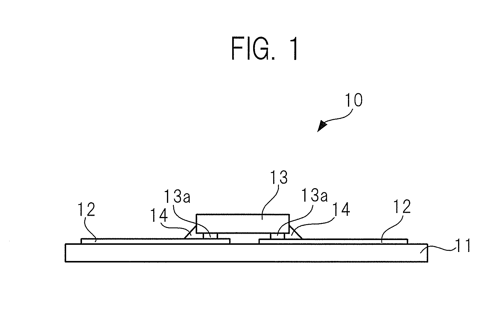
[0089]FIG. 2 illustrates a RFID tag of the present invention. FIG. 2A is a plan view, whereas FIG. 2B is a side view.

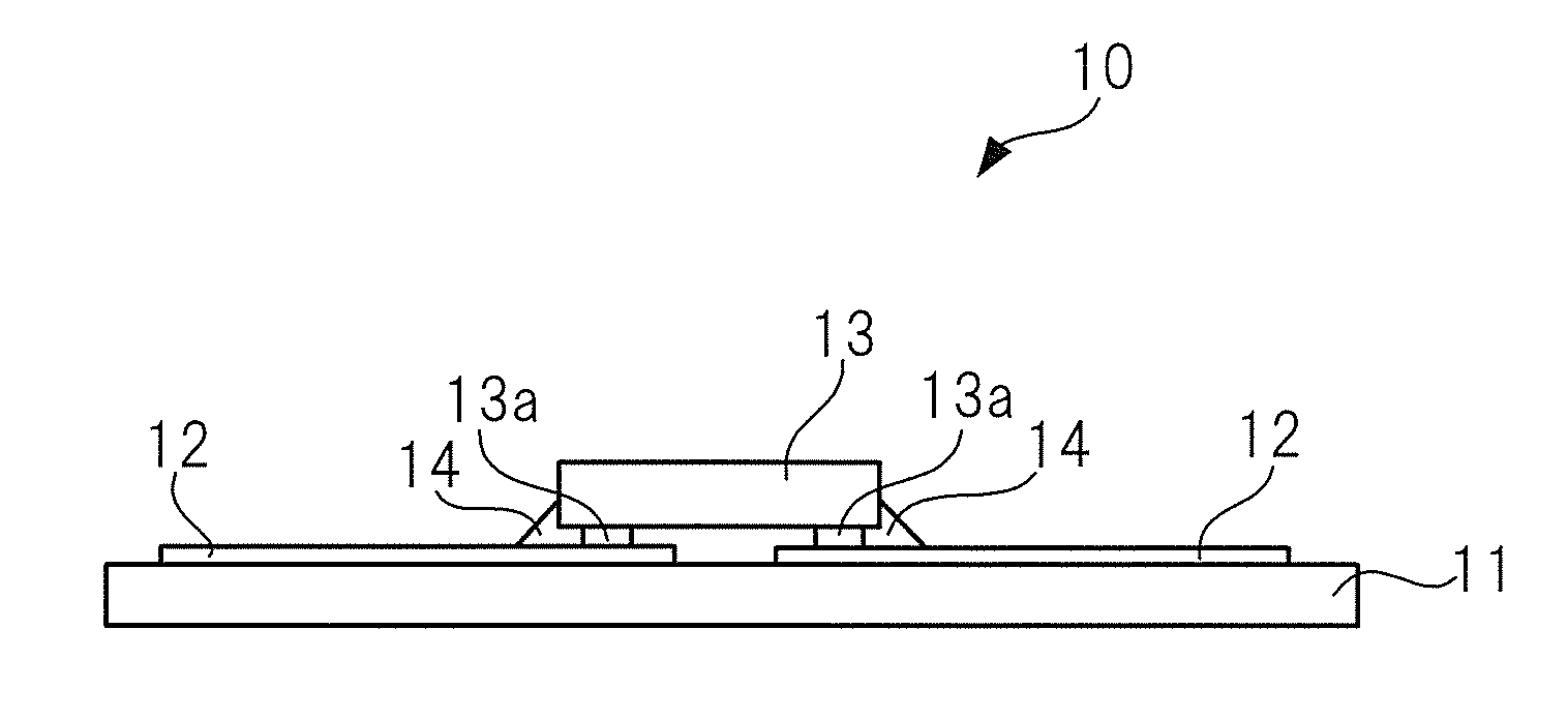
[0090]A RFID tag 100A is composed of an inlay 10 having an antenna 12 and a circuit chip 13 as illustrated in FIG. 1; an enclosure 20 for enclosing the inlay 10; a belt 30 that is integrally formed with the enclosure 20 and extends from the enclosure 20 in right and left directions in FIG. 2; and a spacer 40 that is fixed (here, adhered) to a surface of the enclosure 20 on an article 90 side (see FIG. 3).

[0091]The enclosure 20 and the belt 30 are made of a flexible material like rubber or plastic, and the inlay 10 is completely sealed in the enclosure 20. In one end 30a of the belt 30, notches 30b with bumps are formed, and on the other end 30C of the belt 30, a coupling section 30d having a through hole for letting through the one end 30a is formed.

[0092]The spacer 40 is a single continuous member and made of a material in the form of rubber that follows deformation....

second embodiment

[0117]FIG. 7 illustrates a RFID tag of the present invention.

[0118]Only a spacer 41 is different in a RFID tag 100B illustrated in FIG. 7 as compared to the RFID tag illustrated in FIG. 2. The spacer 41 of the RFID tag 100B illustrated in FIG. 7 is a single continuous member as a whole, made of a foam material in which bubbles are dispersed, for example, rubber foam.

[0119]In general, a rubber material has a large dielectric loss and is apt to lose energy of electromagnetic waves, so that a communication distance is short. As such, here, the spacer 41 is made of a foam material such as rubber foam, for allowing air to be present inside the spacer 41 to suppress reduction in a communication distance. Although a rubber material has a dielectric rate of substantially 3 to 5 in general, it is possible to reduce an actual dielectric rate substantially to 2 by having air in a part. This improves an antenna gain without downsizing the antenna 12 to the extent of unnecessary dimensions.

third embodiment

[0120]FIG. 8 illustrates a RFID tag of the present invention, and FIG. 9 illustrates a state in which the RFID tag illustrated in FIG. 8 surrounds an article.

[0121]Also in a RFID tag 100C illustrated in FIG. 8, only a spacer 42 is different, as compared to the RFID tag 100A illustrated in FIG. 2. The spacer 42 of the RFID tag 100C illustrated in FIG. 8 is a single continuous member having a structure in which rigid members 42d made of a material such as plastic are dispersedly arranged in a flexible member 42a made of a material such as rubber. As such, when the RFID tag 100C surrounds the article 90, by the rigid members 42d dispersedly arranged in the spacer 42, a spacing between the antenna 12 constituting the inlay 10 and the article 90 is controlled irrespective of a wrapping strength of the belt 30, so that a predetermined antenna characteristics can be obtained.


PUM

PropertyMeasurementUnit
communication distanceaaaaaaaaaa
thicknessaaaaaaaaaa
thicknessaaaaaaaaaa

Abstract

The present invention relates to a RFID (Radio Frequency IDentification) tag for exchanging information with an external device in a non-contact manner, and aims to provide a RFID tag having an external shape of a belt, which fits articles made of various kinds of materials. The RFID tag includes: an inlay having an antenna and a circuit chip incorporating a communication circuit for wireless communications via the antenna, an enclosure that encloses the inlay, a flexible belt that surrounds an article to attach the enclosure to the article, and a spacer fixed to a surface of the enclosure on the article side, deforming in response to deformation of the belt to maintain a spacing between the article and the enclosure.

Description

CROSS-REFERENCE TO RELATED APPLICATION[0001]This is a continuation application of PCT / JP2007 / 063437, filed on Jul. 5, 2007.TECHNICAL FIELD [0002]The present invention relates to a RFID (Radio Frequency IDentification) tag that exchanges information with an external device in a non-contact manner and a manufacturing method of the RFID tag.BACKGROUND ART [0003]In recent years, there are proposed various types of RFID tag that exchanges information by radio waves in a non-contact manner with an external device represented by a reader-writer (see Japanese Laid-open Patent Publication Nos. 2000-311226, 2000-200332 and 2001-351082, for example).[0004]FIG. 1 is a schematic cross-sectional diagram illustrating one example of an inner component member (inlay) constituting a RFID tag.[0005]An inlay 10 for a RFID tag in FIG. 1 is formed such that on an antenna base 11 made of, for example, PET film or the like that can bend, an antenna 12 made of a conductive pattern is formed and further a ci...

Claims


Application Information

Patent Timeline
Patent Type & Authority Applications(United States)
IPC IPC(8): G08B13/14B29C65/70
CPCG06K19/07749
Inventor BABA, SHUNJIHASHIMOTO, SHIGERUSUGIMURA, YOSHIYASUNIWATA, TSUYOSHINOGAMI, SATORUMANIWA, TORU
Owner FUJITSU LTD
Why Eureka
Try Eureka