
X-ray analysis apparatus and method

a technology of x-ray analysis and apparatus, applied in the direction of material analysis using wave/particle radiation, instruments, diaphragm/collimeter handling, etc., can solve the problem of more likely to be absorbed by x-rays, and inability to precisely determine the analysis position

Inactive Publication Date: 2005-11-15
HORIBA LTD
View PDF7 Cites 26 Cited by
  • Summary
  • Abstract
  • Description
  • Claims
  • Application Information

AI Technical Summary

Benefits of technology

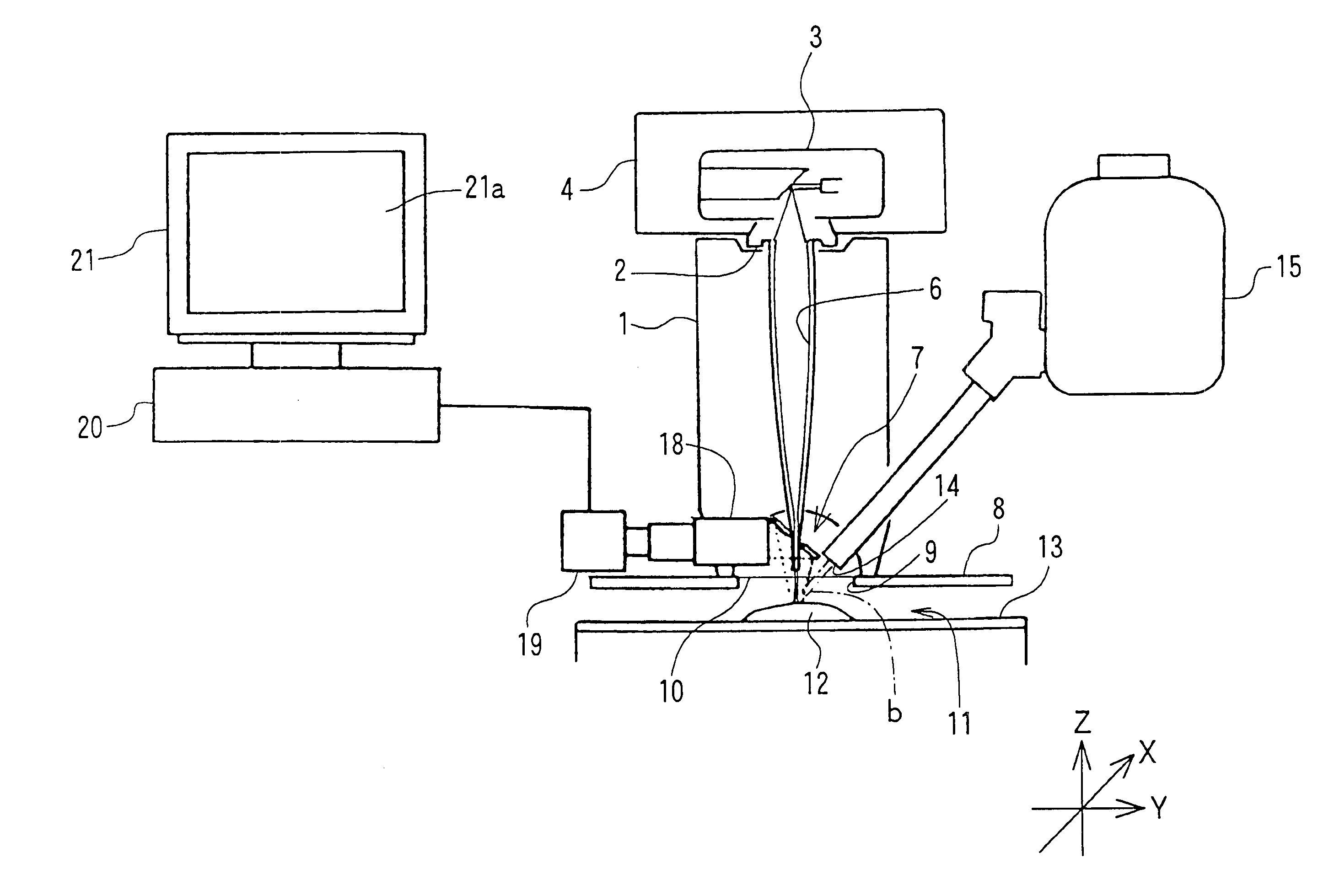
[0010]Using the above-described apparatus, it is possible to obtain an optical image of a sample coaxially with the axis of irradiating the sample with X-rays and perform at the same time the irradiation of the sample with X-rays and the confirmation of an optical image (visible light image) of the sample to be irradiated with X-rays in X-ray analysis of the sample. Therefore, it is possible to confirm, for example, visually the state (situation) of the sample while irradiating the sample with X-rays, and accurately determine the position of analysis even in case that the surface of the sample is uneven. Since a sample is directly irradiated with X-rays for X-ray analysis, the X-rays are not absorbed by a mirror and the analysis sensitivity is not lowered even in light element analysis. Further, since it is possible to make the X-ray output end of an X-ray guide member as close as possible to a sample, it is also possible to prevent the spatial resolution from lowering.
[0014]In an X-ray analysis apparatus made to irradiate a sample with X-rays narrowed down by means of an X-ray guide member from above the sample, it is acceptable also to irradiate directly said sample with X-rays from said X-ray guide member and provide an optical fiber along said X-ray guide member. In such a case, a mirror for reflecting visible light and a collective lens are made unnecessary and thereby the structure is more simplified.

Problems solved by technology

As shown in FIG. 6 described above, however, in an X-ray analysis apparatus made to observe an optical image at an angle with the direction of X-ray irradiation, when the height of a sample is changed, a difference (discrepancy) arises between the position of observing an optical image and the position of X-ray irradiation in the sample 41, and if the surface of the sample is uneven it is not possible to exactly determine the position of analysis.
Particularly, the lower the low-energy X-rays effective for exciting light elements are in energy, the more likely the X-rays are to be absorbed; it is not possible to avoid the lowering of analysis sensitivity in light element analysis.

Method used


Image

  • X-ray analysis apparatus and method
  • X-ray analysis apparatus and method
  • X-ray analysis apparatus and method

Examples


Embodiment Construction

[0024]The following description is provided to enable any person skilled in the art to make and use the invention and sets forth the best modes contemplated by the inventors of carrying out their invention. Various modifications, however, will remain readily apparent to those skilled in the art, since the general principles of the present invention have been defined herein.

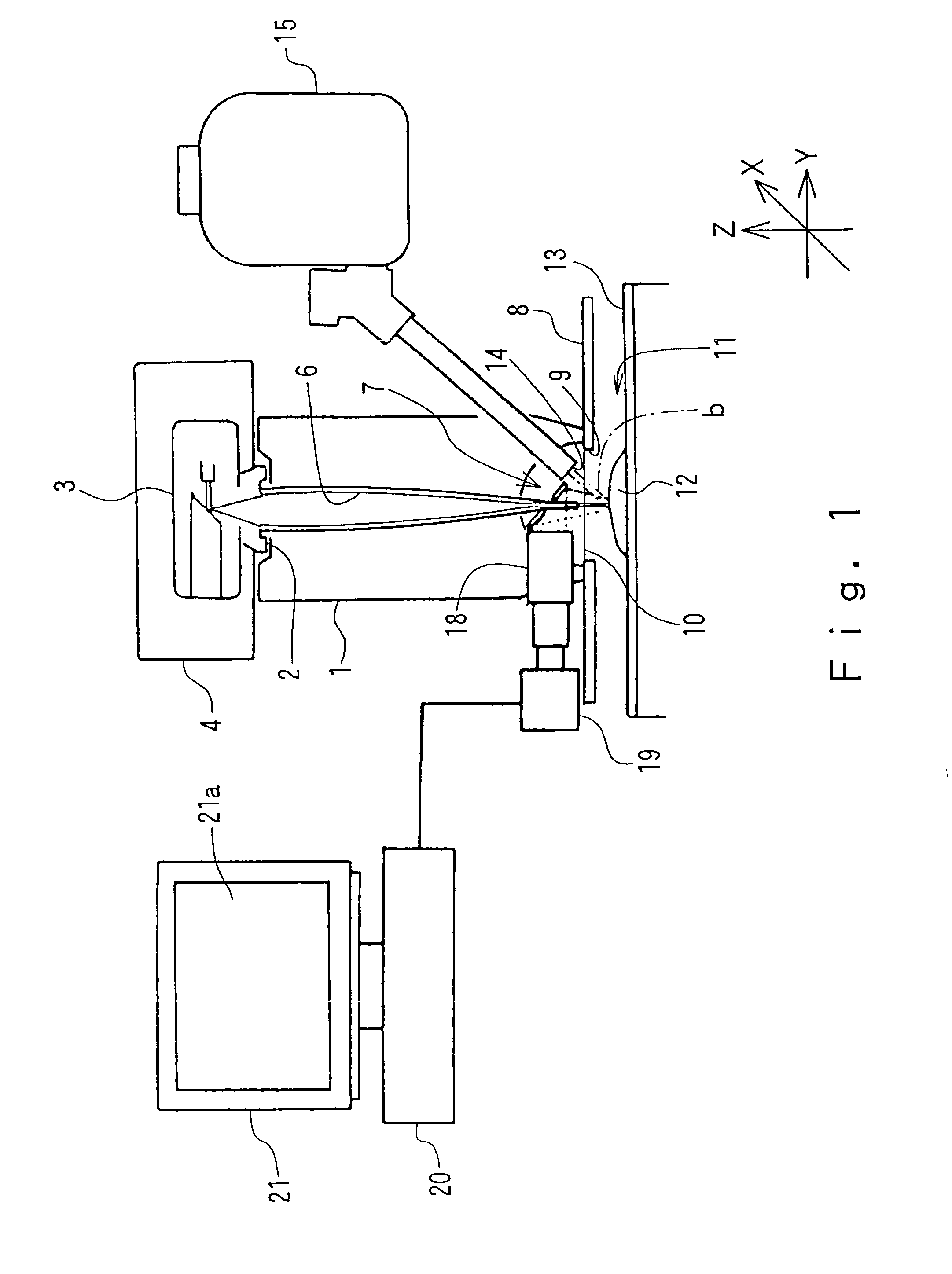
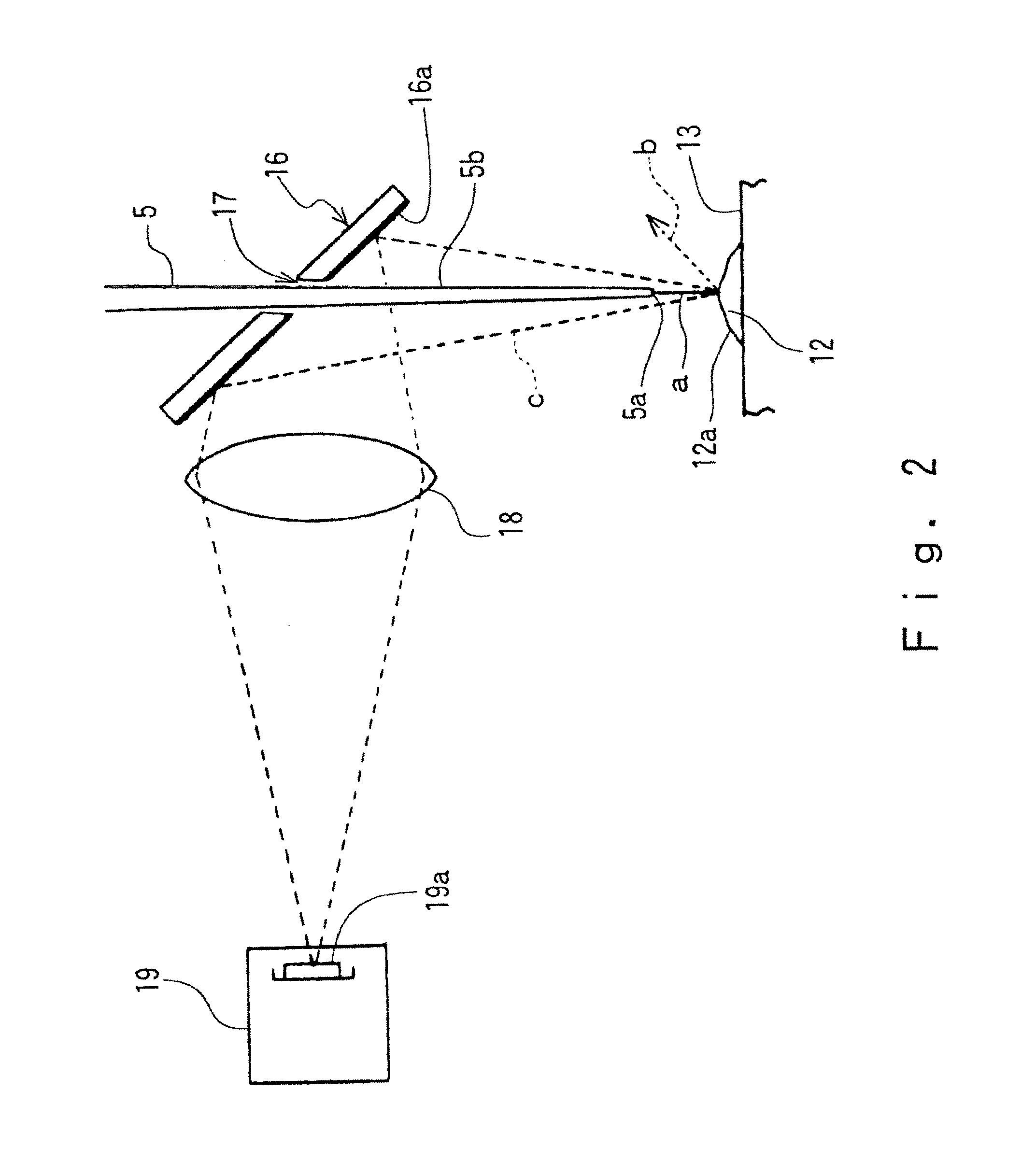
[0025]Details of the present invention are described with reference to the drawings in the following. FIGS. 1 and 2 show an embodiment of the present invention. FIG. 1 shows schematically an example of a main composition of an analysis part of an X-ray analysis apparatus of the present invention, and FIG. 2 is a diagram showing schematically an optical portion of said analysis part. In these figures, number 1 refers to a main body block of an X-ray analysis apparatus, above which there is provided an X-ray generator 4 containing an X-ray tube 3, a power source part (not illustrated) through a seal portion 2. The m...


PUM

PropertyMeasurementUnit
diameteraaaaaaaaaa
lengthaaaaaaaaaa
sizeaaaaaaaaaa

Abstract

This invention provides an X-ray analysis apparatus and method capable of simply and accurately determining the position of analysis in a sample from an optical image of it without lowering the sensitivity and / or the spatial resolution in light element analysis. The X-ray analysis apparatus of the present invention irradiates a sample with X-rays narrowed down by means of an X-ray guide member from above the sample in which said sample is directly irradiated with X-rays from said X-ray guide member and an optical image of said sample is obtained in the direction coaxial with said X-ray guide member.

Description

FIELD OF INVENTION[0001]The present invention relates to an X-ray analysis apparatus and method used for examining samples. More particularly, the invention relates to a method and apparatus for analyzing the kind, amount and distribution state of elements contained in a sample.BACKGROUND OF THE INVENTION[0002]An X-ray analysis apparatus irradiates a sample mounted on a sample stage with primary X-rays, detects secondary X-rays such as fluorescent X-rays, scattering X-rays and the like generated at that time by means of an X-ray detector, processes properly the detected output, and thereby makes it possible to analyze constituent elements of the sample or its internal structure.[0003]Recently a demand for analyzing in more detail a microscopic part of a sample, using the X-ray analysis apparatus as described above, has been increased. To perform this more detailed analysis, a microscopic part of the sample is irradiated with X-rays narrowed down by means of an X-ray guide member suc...

Claims


Application Information

Patent Timeline
Patent Type & Authority Patents(United States)
IPC IPC(8): G01N23/22G01N23/223G21K1/02G21K1/06
CPCG01N23/223G01N2223/076
Inventor OHZAWA, SUMITO
Owner HORIBA LTD
Learn More