System and method for detecting EAS/RFID tags using step listen

a technology of step listen and rfid tag, which is applied in the field of identification tags, can solve the problems of continuous signal emission from the reader, rfid chip, and inferior performance of either technology deployed alone, and achieve the effect of reducing the amplitude of carrier forcing function and avoiding cost and space inefficiencies in duplication circuitry

Inactive Publication Date: 2006-12-12
CHECKPOINT SYST INC
View PDF10 Cites 26 Cited by
  • Summary
  • Abstract
  • Description
  • Claims
  • Application Information

AI Technical Summary

Benefits of technology

[0011]The carrier envelope edge formed during this modulation causes a transient response in any LC resonant circuits in the magnetic field of the system due to the excess stored energy in those tags being dissipated as the carrier forcing function amplitude is reduced. Detection of this stored energy transient (also referred to as the “natural response”) is the essence of RF / EAS detection as deployed in the Assignee's (namely, Checkpoint Systems, Inc.) pulse-listen system, as an example. By using this inherent physical characteristic associated with RFID tag signaling, EAS functionality may be included as a natural inherent aspect of the system. Furthermore, the present invention allows common usage of the majority of the transceiver sections avoiding cost and space inefficiencies in duplication of circuitry as well as a shared antenna structure.
[0012]The system and method of step-listen of the present invention provides advantages in tag throughput, detection performance of both technologies and in manufacturing costs.

Problems solved by technology

However, where identification tags are capable of receiving both EAS and RFID frequencies, the conventional manner in which the respective EAS or RFID signals return from these tags is processed exhibits certain shortcomings or limitations.
Utilizing such a configuration, though, involves: redundancy of components (i.e., duplication of transceiver components, duplication of antennae, etc.); the degree of filtering required is great (estimated at 100 dB) due to the very close proximity in frequency (less than 1 octave) and the relative signal amplitude differences allowable for the 2 transmission bands; the need for 2 antennae results in a much wider structure (roughly double) than for either technology deployed alone; and even with these techniques, performance is inferior than for either technology deployed alone.
), which is incorporated by reference herein, one of the disadvantages of these is that when RFID tags are used, there must be a continuous signal emission from the reader to power the RFID chip.

Method used


Image

  • System and method for detecting EAS/RFID tags using step listen
  • System and method for detecting EAS/RFID tags using step listen
  • System and method for detecting EAS/RFID tags using step listen

Examples


Embodiment Construction

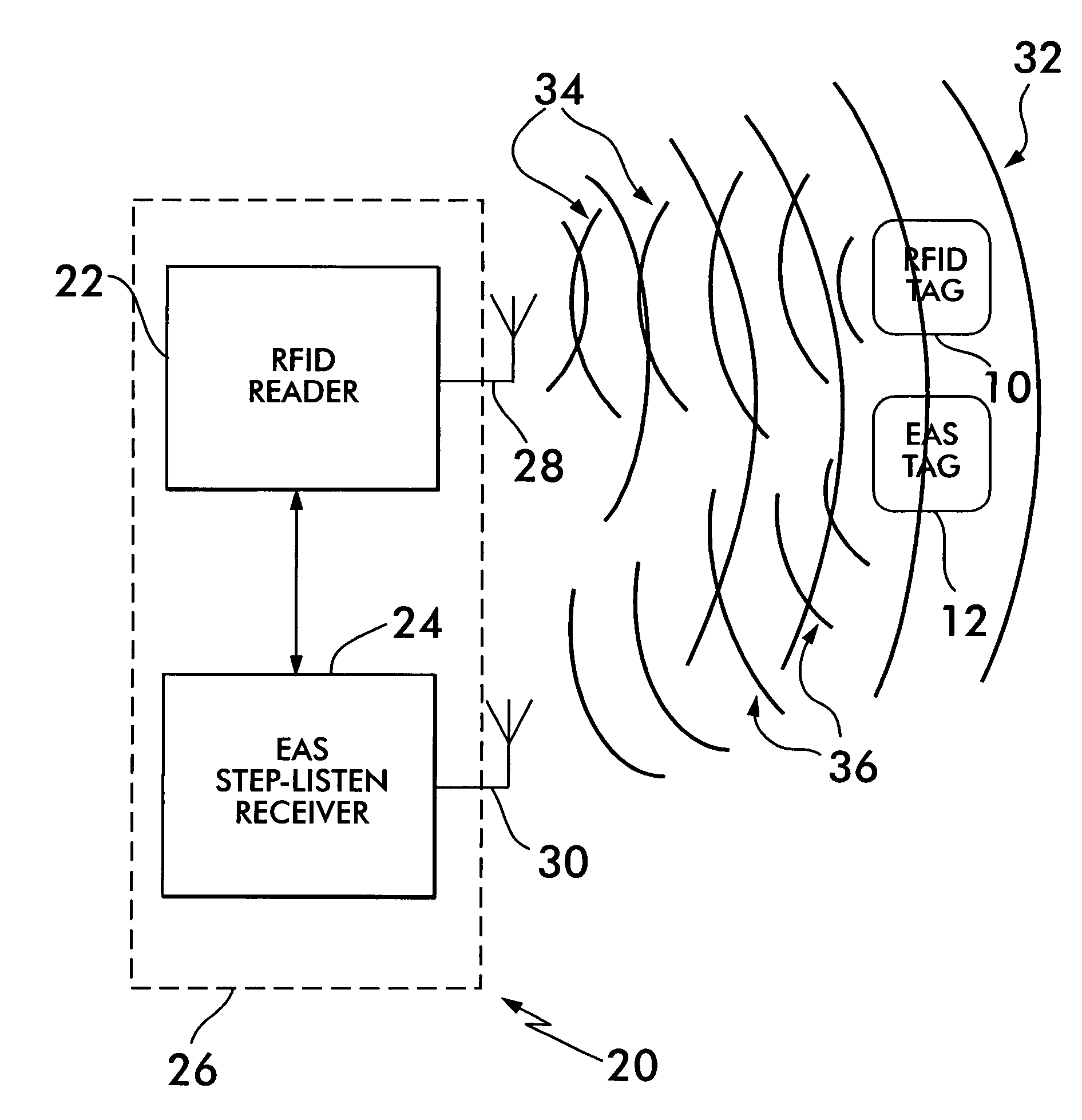
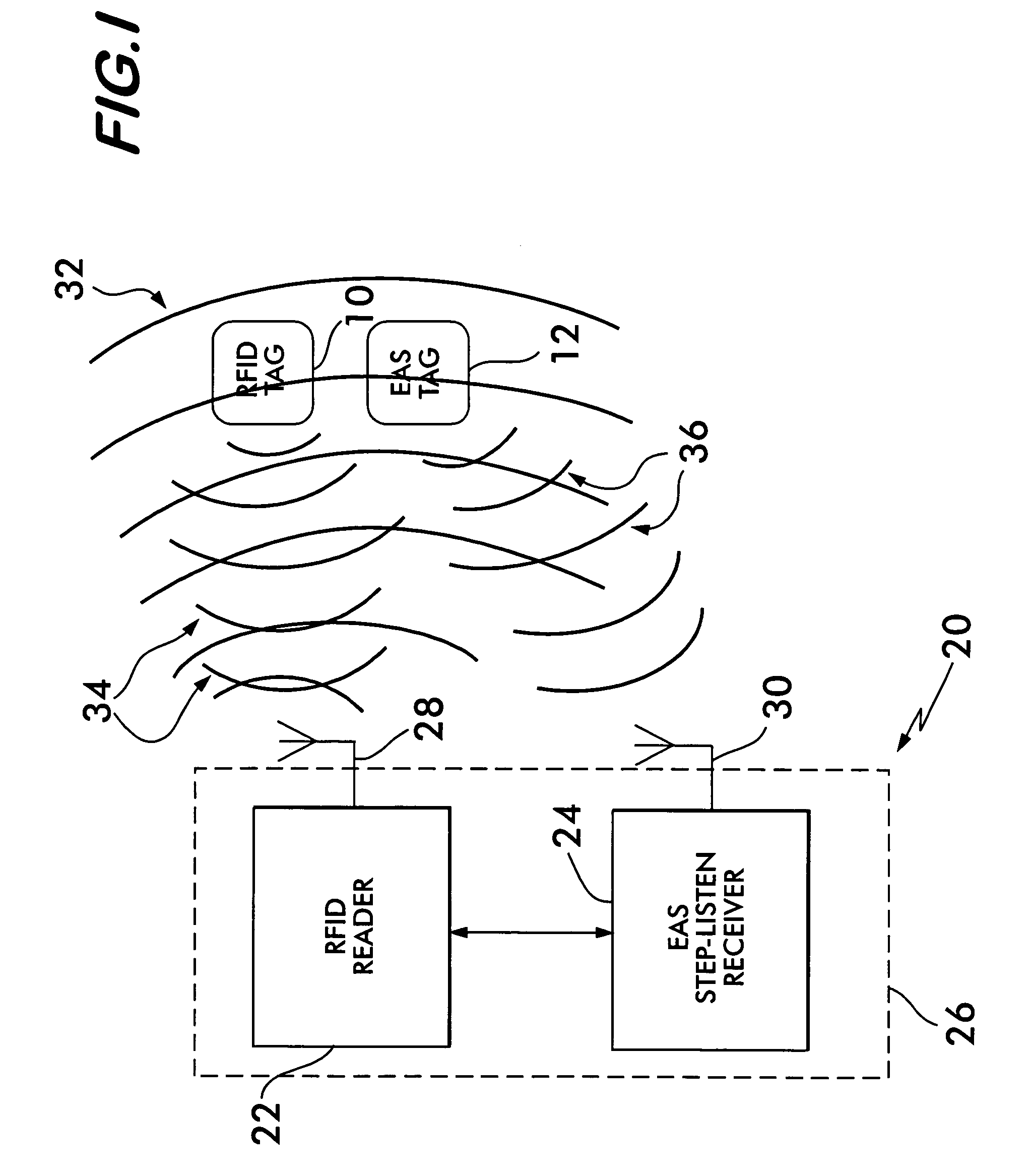
[0035]The present invention 20, as shown in FIG. 1, basically comprises an RFID reader 22 and an EAS step-listen receiver 24 that may be positioned in a single housing 26, and each having respective antennae 28 and 30. In operation, the RFID reader 22 emits the stimulus 32 (FIG. 4) which includes an RFID carrier frequency (e.g., 13.56 MHz), modulated with RTF commands. If an RFID tag 10 is present and is tuned to that RFID frequency, the RFID tag 10 emits a response 34 (FIG. 5) that is detected by the RFID reader 22. If an EAS tag 12 is also present in the vicinity and which is tuned to an EAS frequency (e.g., 8.2 MHz), the EAS tag 12 emits (FIG. 6) a natural response “ring down” signal 36 (caused by the stimulus 32) which is detected by the EAS step-listen receiver 24. It should be understood that the stimulus 32 and the “ring-down” signal 36 are nearly concurrent in time whereas the RFID response 34 occurs later in time.

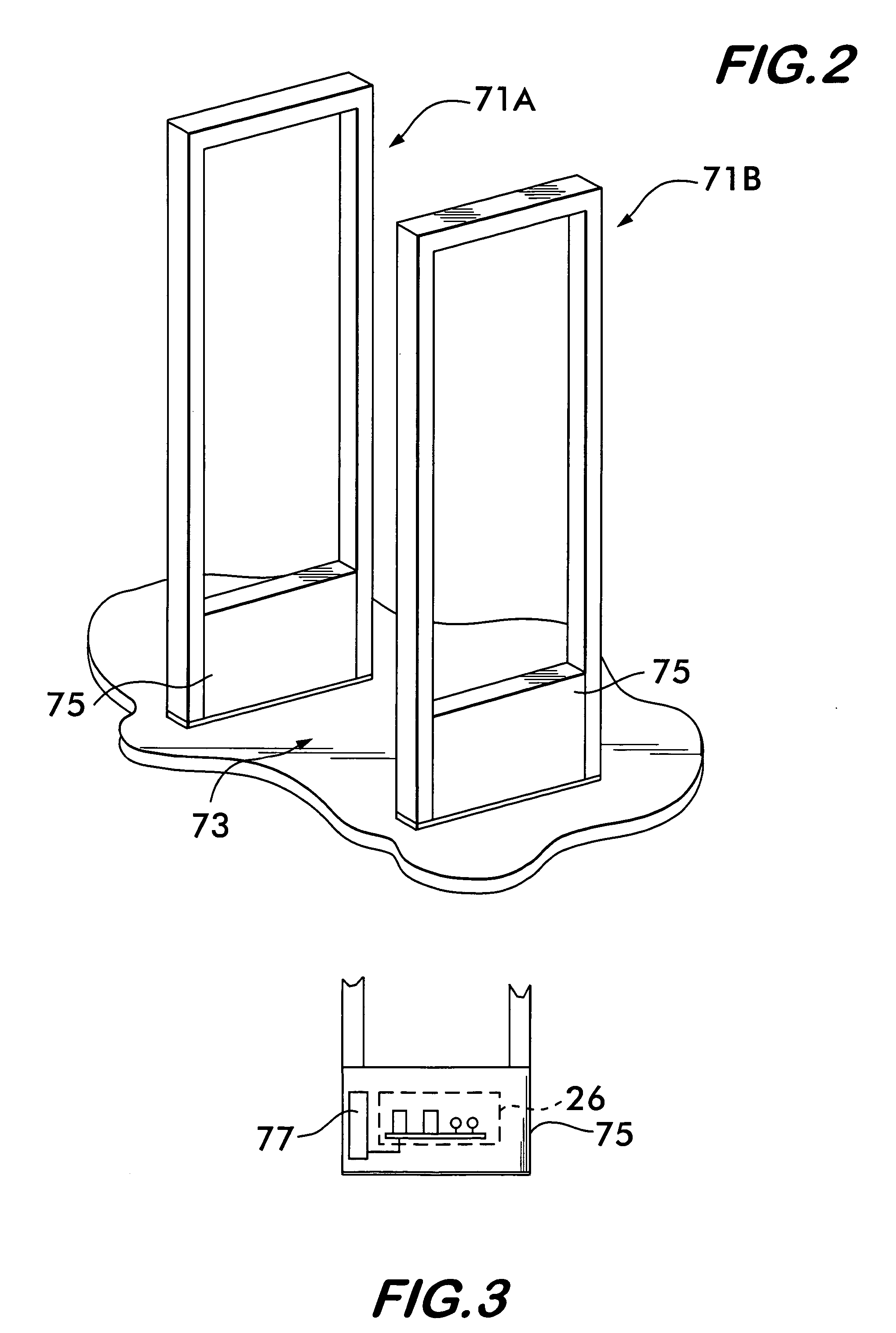
[0036]FIG. 2 depicts an exemplary pair of security pedestals ...


PUM


Abstract

A system and method for the real-time concurrent detection of 13.56 MHz RFID and 8.2 MHz EAS identification tags using a single stimulus signal.

Description

CROSS-REFERENCE TO RELATED APPLICATIONS[0001]This utility application claims the benefit under 35 U.S.C. §119(e) of Provisional Application Ser. No. 60 / 626,063 filed on Nov. 8, 2004 entitled SYSTEM AND METHOD FOR DETECTING EAS / RFID TAGS USING STEP LISTEN and whose entire disclosure is incorporated by reference herein.BACKGROUND OF THE INVENTION[0002]1. Field of Invention[0003]This invention relates generally to identification tags and, more particularly, to a system and method for the simultaneous detection of 8.2 MHz EAS tags and 13.56 MHz ISO15693 RFID Tags.[0004]2. Description of Related Art[0005]The use of EAS (electronic article surveillance) tags and RFID (radio frequency identification) tags for a wide variety of read, track and / or detect applications is rapidly expanding. A smooth bridge between existing EAS and RFID functionality has been a consistent theme identified by users interested in RFID to allow them to obtain the benefits of RFID while maintaining their investment...

Claims


Application Information

Patent Timeline
Patent Type & Authority Patents(United States)
IPC IPC(8): G08B13/14
CPCG08B13/2417G08B13/2448G08B13/2471G06K7/00G06K19/00
Inventor SALESKY, RONALDPARANZINO, JOHNSHAH, NIMESH
Owner CHECKPOINT SYST INC
Why Eureka
Try Eureka