Headset And A Method For Audio Signal Processing

Active Publication Date: 2015-06-18
GN NETCOM
View PDF2 Cites 20 Cited by
  • Summary
  • Abstract
  • Description
  • Claims
  • Application Information

AI Technical Summary

Benefits of technology

[0012]In general, different types of microphones with different characteristics may be selected.
[0013]A desired signal is a signal that typically represents voice from a speaker within proximity of the microphones or voice appearing from a certain direction relative to the orientation of the microphones. A desired signal may be characterised by being emitted from one or more sound sources having predefined spatial locations with respect to the spatial location of the microphones. Since multiple microphones are used to pick up the desired signal the desired signal may be characterised by a predefined phase and/or amplitude difference among the microphone signal and/or among beamformed signals. A desired signal may also be characterised by a predefined temporal characteristic and/or a predefined phase-/amplitude-frequency characteristic.
[0014]A noise signal or simply noise may include turbulence sounds induced by wind occurring at sufficiently high wind speeds and acting on the microphone membranes. Noise may also include background sounds such as tones from machines, sounds from items rattling or chinking, sounds from people talking amongst each other, etc. In some definitions, noise is characterised by being emitted from one or more sound sources that are located at other locations than the desired signal.
[0015]The first beamformer and the second beamformer adapt the directional sensitivity gradually or in steps e.g. comprising sensitivities that are at least approximated from the group of the following characteristics: Omni-directional, bi-directional, cardio

Problems solved by technology

Furthermore, the first and the second beamformers may not be able to cancel the noise equally well, depending on the relative position of the microphone pair, the signal of interest and interfering noises.
As a consequence, t

Method used


Image

  • Headset And A Method For Audio Signal Processing
  • Headset And A Method For Audio Signal Processing
  • Headset And A Method For Audio Signal Processing

Examples


Example

[0060]In the following description, reference is made to the accompanying figures, which show, by way of illustration, how the invention may be practiced.

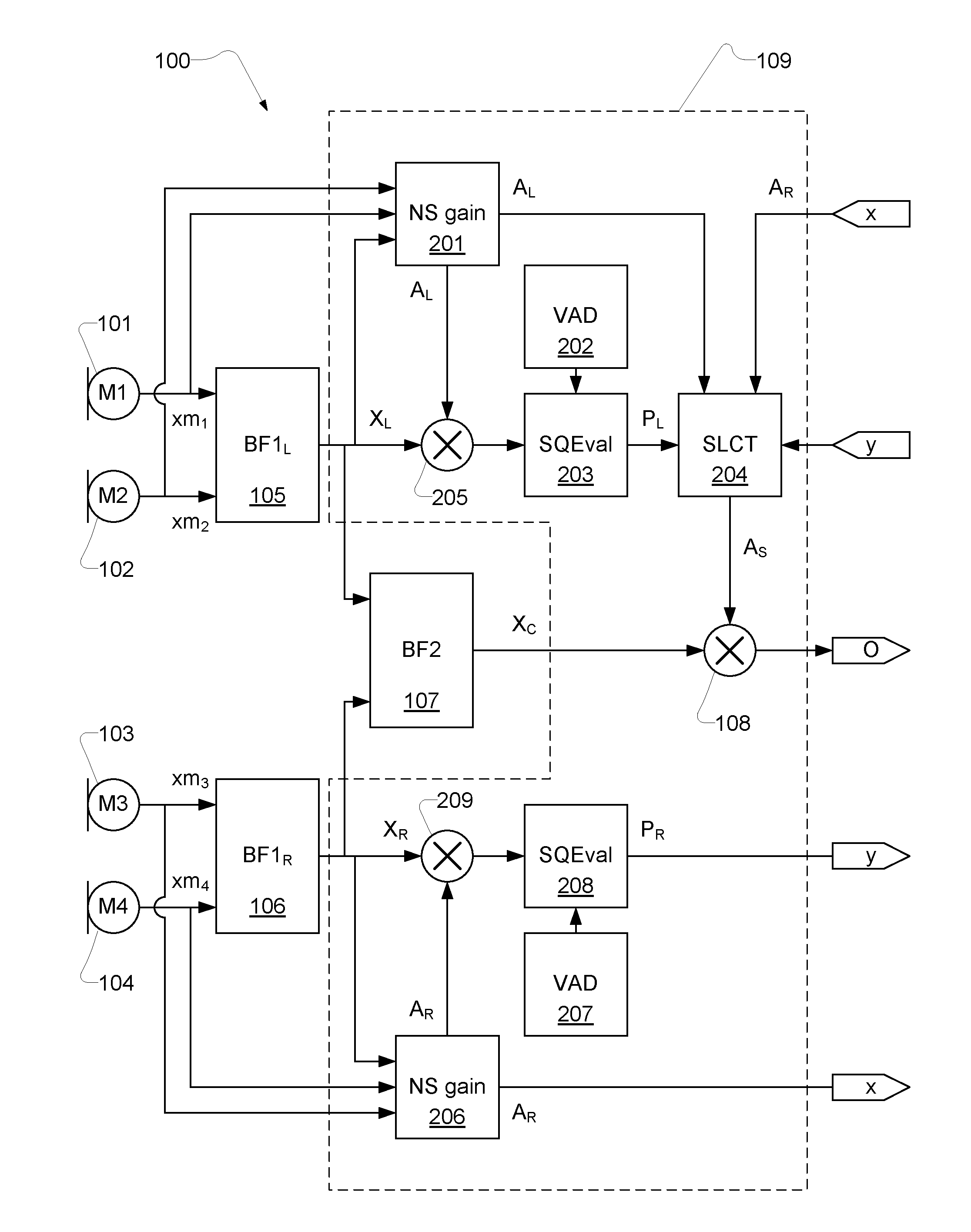
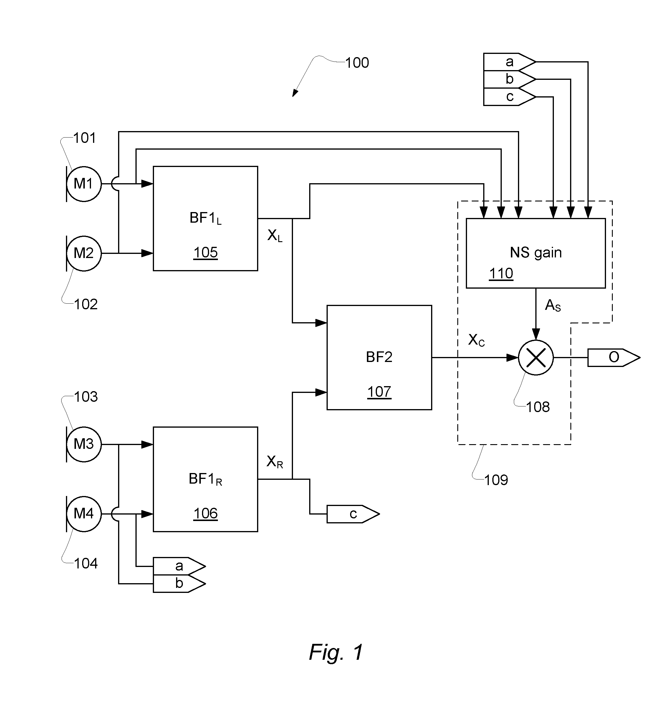
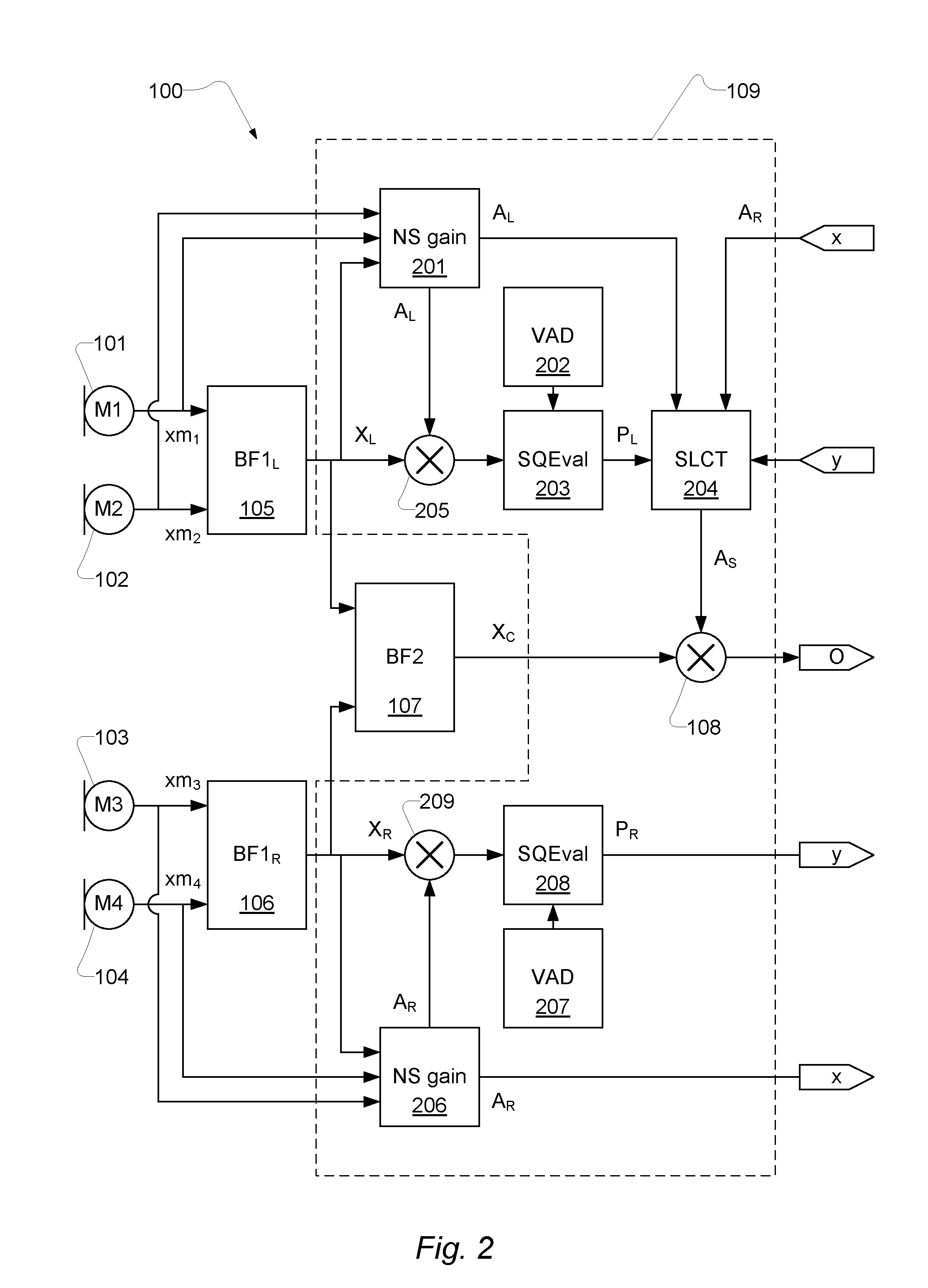
[0061]FIG. 1 shows a block diagram of a signal processor and a first and second pair of microphones. The first set of microphones, 101 and 102, and the second set of microphones, 103 and 104, are arranged with an intra-pair distance between the microphones that is relatively short compared to the microphone pairs inter-distance, between the pairs of microphones. The signal processor is designated by reference numeral 100.

[0062]The first pair of microphones 101 and 102 outputs a first microphone signal pair input to a first beamformer 105 and the second pair of microphones 103 and 104 outputs a second microphone signal pair, which is input to a second beamformer 106. The first beamformer 105 and the second beamformer 106 outputs respective output signals XL and XR.

[0063]The first beamformer 105 and the second beamformer 106 are each...


PUM


Abstract

A headset and a method configured to process audio signals from multiple microphones, comprising: a first pair of microphones (101,102) outputting a first pair of microphone signals and a second pair of microphones (103, 104) outputting a second pair of microphone signals; a first near-field beamformer (105) and a second near-field beamformer (106) each configured to receive a pair of microphone signals and adapt the spatial sensitivity of a respective pair of microphones as measured in a respective beamformed signal (XL; XR) output from a respective beamformer (105; 106); wherein the spatial sensitivity is adapted to suppress noise relative to a desired signal; a third beamformer (107) configured to dynamically combine the signals (XL; XR) output from the first beamformer (105) and the second beamformer (106) into a combined signal (XC); wherein the signals are combined such that signal energy in the combined signal is minimized while a desired signal is preserved; and a noise reduction unit (109) configured to process the combined signal (XC) from the third beamformer (107) and output the combined signal such that noise is reduced.

Description

[0001]It has been discovered that use of multiple microphones and the use of beamforming techniques provide audio signal reproduction that is superior to single microphone or non-beamforming systems. The multiple microphones are located at different positions and allows so-called spatial sampling which in turn enables cancelling of noise interfering with a desired signal such as a person's voice; this is also known as beamforming, spatial filtering or noise-cancelling. Subsequent time varying post-filters are often applied as a means to further discriminate the person's voice from (background) noise signals.[0002]Multiple microphones and the use of beamforming techniques are frequently embodied in headsets, hearing aids, laptop computers and other electronic consumer devices.[0003]The technical field of beamformers has been extensively researched; however their qualities and configurations have not been fully exploited.RELATED PRIOR ART[0004]US 2012 / 0020485 discloses an audio signal...

Claims


Application Information

Patent Timeline
IPC IPC(8): G10K11/175
CPCG10K11/175G10L21/0208G10L2021/02166H04R1/406H04R3/005H04R2201/107H04R1/1091H04R2201/10
Inventor OLSSON, RASMUS KONGSGAARD
Owner GN NETCOM
Why Eureka
Try Eureka