Plasma display device and driving method for stabilizing address discharge

A technology for plasma and display devices, used in identification devices, static indicators, instruments, etc.

Inactive Publication Date: 2006-05-17
SAMSUNG SDI CO LTD
View PDF0 Cites 4 Cited by
  • Summary
  • Abstract
  • Description
  • Claims
  • Application Information

AI Technical Summary

Problems solved by technology

However, in this case, overdischarge may occur during the address discharge that occurs during the address period after the master reset period

Method used


Image

  • Plasma display device and driving method for stabilizing address discharge
  • Plasma display device and driving method for stabilizing address discharge
  • Plasma display device and driving method for stabilizing address discharge

Examples


Embodiment Construction

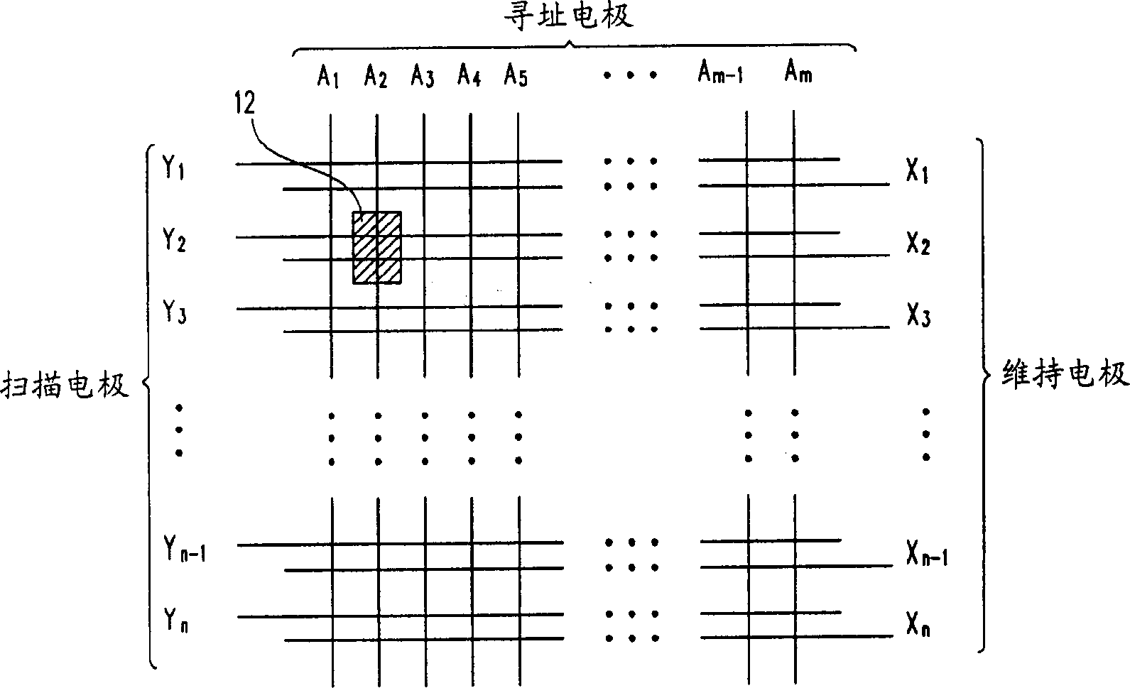
[0022] figure 2 A schematic diagram of electrode arrangement of a PDP according to an embodiment of the present invention is shown. The electrodes of the PDP are arranged in an n×m matrix form. Addressing electrode A 1 to A m arranged in the column direction, while the scan electrodes Y 1 to Y n and sustain electrode X 1 to x n Arranged in pairs in the row direction. Discharge cells (hereinafter referred to as discharge cells) 12 are formed by discharge spaces formed at intersection regions of the address electrode A and a pair of scan and sustain electrodes Y, X. Referring to FIG.

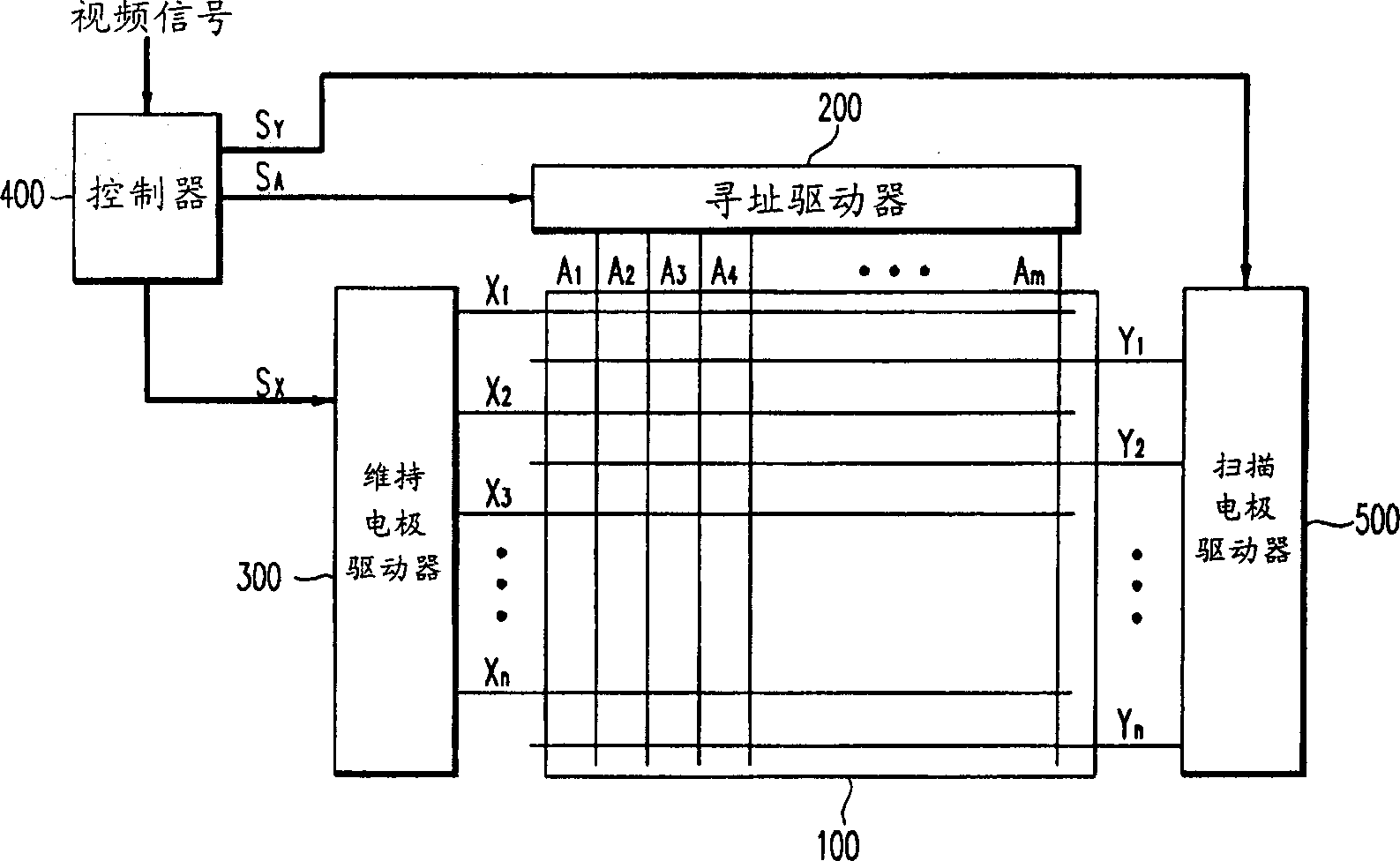
[0023] image 3 A schematic diagram of a plasma display device according to an embodiment of the present invention is shown. A plasma display device according to an embodiment of the present invention includes a plasma panel 100 , an address driver 200 , a scan electrode driver 500 , a sustain electrode driver 300 , and a controller 400 .

[0024] The plasma panel 100 includes a plurali...


PUM


Abstract

The present invention provides a method of driving a plasma display device through a plurality of subfields divided from a frame when different driving waveforms are applied during reset periods of the plurality of subfields. During the address period, by adjusting the bias voltage applied to the sustain electrode according to the driving waveform of the previous reset period, it is possible to prevent defective addressing that may be caused by the unstable wall charge state remaining at the end of the reset period operate.

Description

technical field [0001] The present invention relates to a plasma display device, and more particularly, to a driving method for stably generating address discharge. Background technique [0002] A plasma display device is a flat panel display device that displays characters and images using plasma generated by a gas discharge process. It includes a Plasma Display Panel (PDP) with tens of millions of pixels provided in a matrix in accordance with the size of the PDP. [0003] According to a typical driving method of a PDP, each frame is divided into a plurality of subfields, and a displayed image is represented by a combination of subfields. Each subfield has a reset period, an address period, and a sustain period. In the reset period, the wall charges formed by the previous sustain discharge are erased, and the wall charges are established so that the following addressing can be stably performed. The address period is for selecting on / off discharge cells (ie, discharge ce...

Claims


Application Information

Patent Timeline
Patent Type & Authority Applications(China)
IPC IPC(8): G09G3/292G09F9/313G09G3/20G09G3/288G09G3/291G09G3/293G09G3/294G09G3/298H01J17/49
CPCG09G3/2022G09G3/2927G09G3/293G09G3/292G09G3/296
Inventor 金明观
Owner SAMSUNG SDI CO LTD
Why Eureka
Try Eureka