Plasma display and driving method thereof

A plasma and driving method technology, applied in the direction of AC plasma display panels, static indicators, gas discharge tubes/containers, etc., can solve the problems of reduced discharge efficiency and other issues

Inactive Publication Date: 2008-05-28
SAMSUNG SDI CO LTD
View PDF0 Cites 1 Cited by
  • Summary
  • Abstract
  • Description
  • Claims
  • Application Information

AI Technical Summary

Problems solved by technology

However, as the number of discharge cells increases, the total capacitance increases, while the discharge efficiency decreases due to the decrease in discharge cell size

Method used


Image

  • Plasma display and driving method thereof
  • Plasma display and driving method thereof
  • Plasma display and driving method thereof

Examples


Embodiment Construction

[0026] In the following detailed description, only some exemplary embodiments of the present invention are shown and described, by way of simple examples. As those skilled in the art would realize, the described embodiments may be modified in various different ways, all without departing from the spirit and scope of the present invention. Accordingly, the drawings and description thereof should be regarded as illustrative in nature and not restrictive. Throughout the specification, the same reference numerals refer to the same parts.

[0027] A plasma display constructed as an exemplary embodiment according to the principles of the present invention and a driving method thereof will now be described with reference to the accompanying drawings.

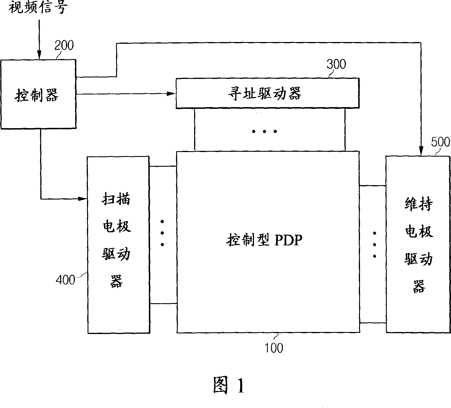
[0028] FIG. 1 shows a plasma display constituting an exemplary embodiment of the present invention. As shown in FIG. 1 , a plasma display according to an exemplary embodiment of the present invention is configured with a control type...


PUM


Abstract

A plasma display and a driving method for the plasma display. The plasma display is constructed with a control type plasma display panel having a closed barrier rib configuration, and each pair of column-wise neighboring discharge cells have different electrode arrangement. In the driving method, when the control type plasma display panel has an alignment error for a first electrode and a second electrode, a scan pulse having a first width is applied to an odd-numbered first electrode, and the scan pulse having a second width that is different from the first width is applied to an even-numbered first electrode.

Description

technical field [0001] The present invention relates to a plasma display and its driving method. Background technique [0002] A plasma display employs a plasma display panel (PDP) configured to display moving characters and / or video images using plasma generated by gas discharge, and has higher brightness, larger High luminous efficiency and wider viewing angle. Accordingly, plasma displays are gaining prominence as a replacement for conventional cathode ray tubes (CRTs) as large-screen displays exceeding 40 inches. [0003] Generally, a plasma display panel (PDP) of a plasma display includes a plurality of address electrodes (hereinafter referred to as A electrodes) extending in a column direction, and a plurality of sustain electrodes and scan electrodes (hereinafter referred to as A electrodes) extending in pairs in a row direction. are called X electrodes and Y electrodes, respectively). The A electrode intersects with the X and Y electrodes. The structure in which ...

Claims


Application Information

Patent Timeline
Patent Type & Authority Applications(China)
IPC IPC(8): G09G3/28G09G3/20H01J17/49G09F9/313G09G3/288G09G3/291G09G3/293G09G3/296G09G3/298H01J11/12H01J11/22H01J11/24H01J11/26H01J11/34H01J11/36H01J11/42H01J11/50
CPCH01J11/24G09G3/293G09G2300/04H01J2211/323H01J2211/245G09G2320/0223G09G2310/0218H01J11/12H01J11/32G09G2300/0426
Inventor 金泰显
Owner SAMSUNG SDI CO LTD
Why Eureka
Try Eureka