Spark-ignition four-stroke engine

A four-stroke engine, spark ignition technology, applied in spark ignition controllers, engine ignition, engine components, etc., can solve problems such as poor ignition, easy cooling of the ignition plug, and smoke from the ignition plug

Inactive Publication Date: 2002-02-27
HONDA MOTOR CO LTD
View PDF1 Cites 2 Cited by
  • Summary
  • Abstract
  • Description
  • Claims
  • Application Information

AI Technical Summary

Problems solved by technology

[0004] In order to improve the combustibility of the mixed gas, it is a well-known technology to form a swirl in the fuel chamber and install an intake port on the cylinder head. When installing several ignition plugs facing the same combustion chamber on the cylinder head

Method used


Image

  • Spark-ignition four-stroke engine
  • Spark-ignition four-stroke engine
  • Spark-ignition four-stroke engine

Examples


Embodiment Construction

[0018] Hereinafter, embodiments of the present invention will be described with reference to an embodiment of the present invention shown in the accompanying drawings.

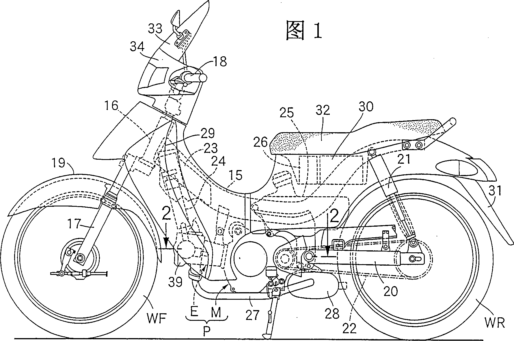
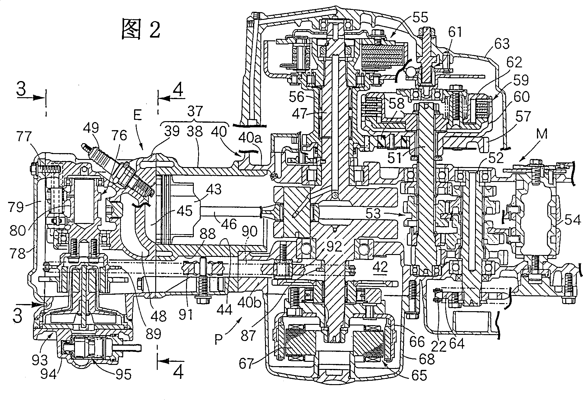
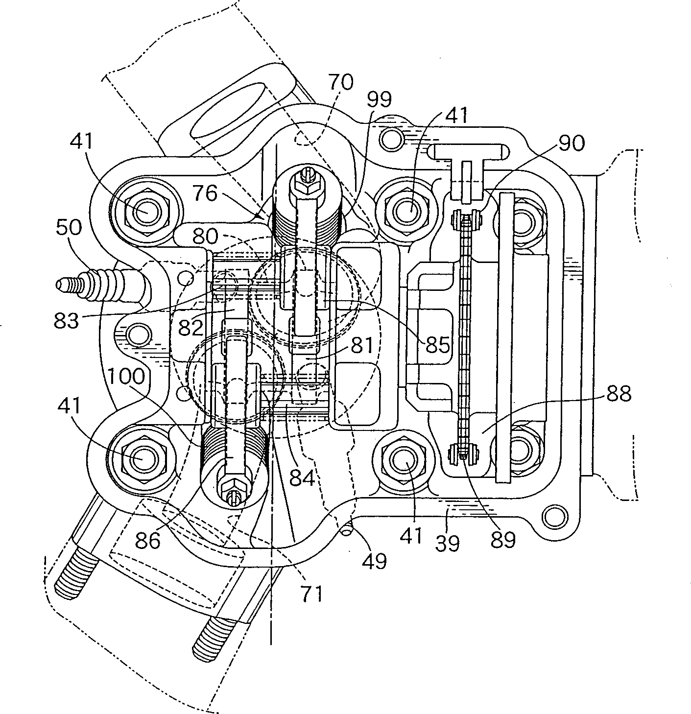
[0019] Figure 1 to Figure 8 An example of the present invention is shown. Fig. 1 is a side view of a two-wheeled motor vehicle. Fig. 2 is a sectional view of the power unit along line 2-2 in Fig. 1 . image 3 It is an enlarged view of line 3-3 in Figure 2. Figure 4 It is the magnified sectional view of line 4-4 in Fig. 2. Figure 5 yes Figure 4 The 5-5 line section diagram. Figure 6 yes Figure 5 6-way view in . Fig. 7 is a projection view of the intake port toward a plane perpendicular to the axis of the cylinder bore. Figure 8 yes Figure 5 The 8-8 line section diagram.

[0020] As shown in FIG. 1, a front end of a frame 15 of a motorcycle is provided with a head pipe 16, and a front fork 17 pivotally supporting a front wheel WF is pivotally supported on the head pipe 16 in a steerable manner. ...


PUM


Abstract

The invention provides a spark-ignition four-stroke engine, in which a plurality of ignition plugs facing the same combustion chamber are mounted on a cylinder head, which can prevent ignition failure by an ignition plug . An intake port 70 is mounted on a cylinder head 39 to enable to produce a swirl in a combustion chamber 45, and the heating value becomes higher as the ignition plugs are apart from the intake port 70 along the flow direction of the swirl in the combustion chamber 45.

Description

technical field [0001] The invention relates to spark ignition four-stroke engines in which several ignition plugs facing the same fuel chamber are mounted on the cylinder head. Background technique [0002] In the prior art, such a four-stroke engine has, for example, the type disclosed in Japanese Patent Application Laid-Open No. H10-500750. [0003] In the above-mentioned conventional engine, in order to reduce fuel consumption and improve exhaust performance, a plurality of ignition plugs are installed on the cylinder head avoiding the intake valve and the exhaust valve. [0004] In order to improve the combustibility of the mixed gas, it is a well-known technology to form a swirl in the fuel chamber and install an intake port on the cylinder head. When installing several ignition plugs facing the same combustion chamber on the cylinder head of the cylinder that generates the swirl , The mixed gas coming in from the suction port flows into the combustion chamber and imm...

Claims


Application Information

Patent Timeline
IPC IPC(8): F02P15/08F02B23/08F02B31/00F02F1/24F02F1/42F02P15/02
CPCY02T10/146Y02T10/125Y02T10/12
Inventor 菊池一纪饭嶌智司久保田良
Owner HONDA MOTOR CO LTD
Why Eureka
Try Eureka