
Cyclonic vacuum cleaner

A technology for vacuum cleaners and vacuum cleaners, applied in the directions of vacuum cleaners, suction filters, cleaning equipment, etc., can solve the problems of increasing the volume of a dust container 20, and achieve the effect of increasing the dust collection capacity

Inactive Publication Date: 2006-05-24
SAMSUNG GWANGJU ELECTRONICS CO LTD
View PDF0 Cites 3 Cited by
  • Summary
  • Abstract
  • Description
  • Claims
  • Application Information

AI Technical Summary

Problems solved by technology

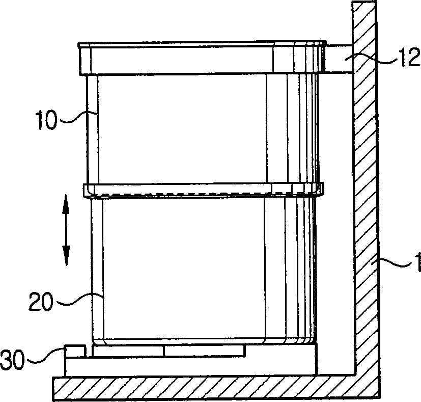
However, in order to increase the volume of the dust container 20, the overall size of the cleaner body 1 needs to be increased accordingly.

Method used


Image

  • Cyclonic vacuum cleaner
  • Cyclonic vacuum cleaner
  • Cyclonic vacuum cleaner

Examples


Embodiment Construction

[0026] Hereinafter, specific embodiments of the present invention will be described in detail with reference to the accompanying drawings. Definitions such as detailed structures and elements are defined in the description to assist understanding of the present invention. Well-known functions or constructions are not described in detail since they would obscure the invention in unnecessary detail.

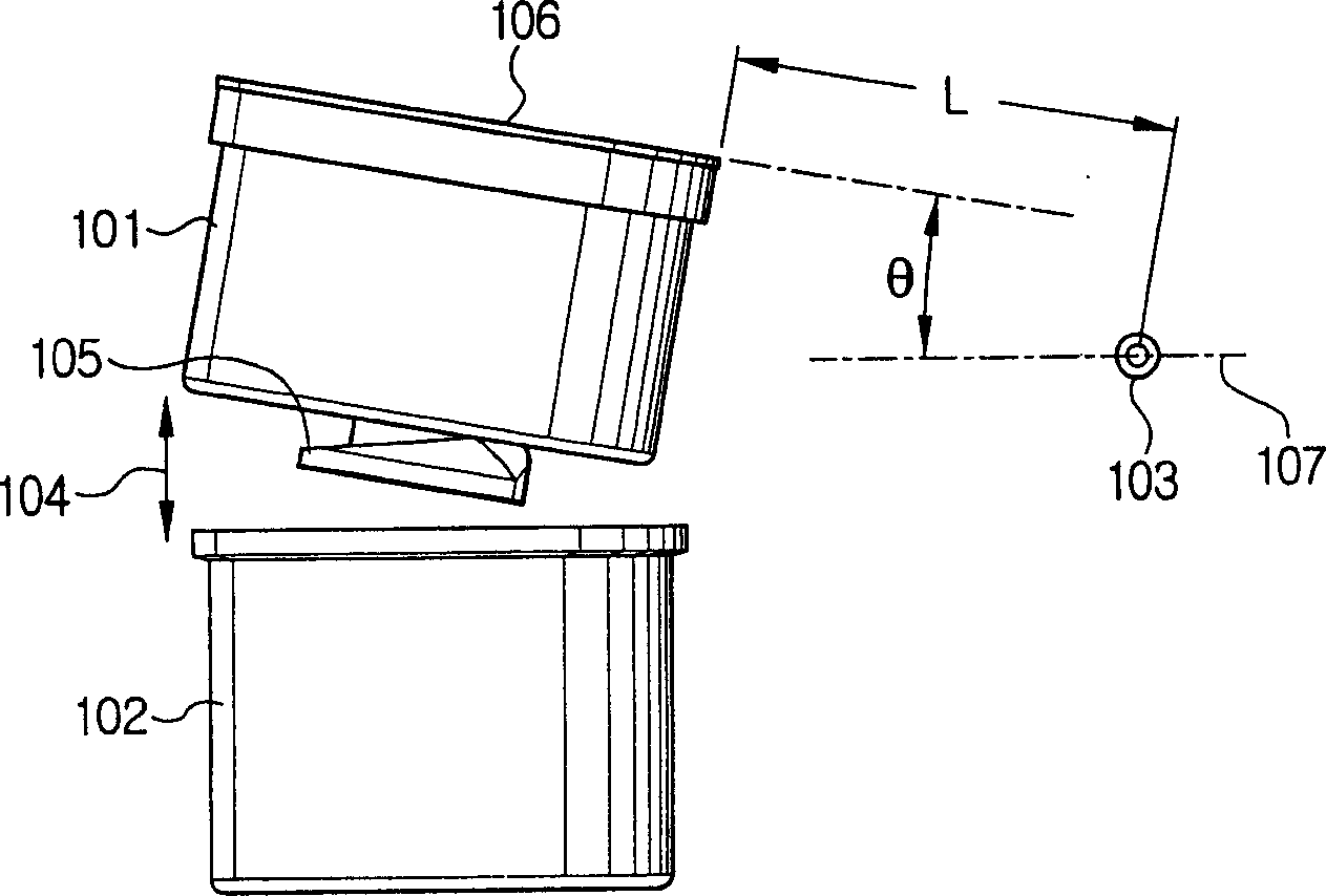
[0027] figure 2 The concept of a cyclonic dust collector of a cyclonic vacuum cleaner according to an embodiment of the present invention is shown. Since the structure of the vacuum cleaner body of a vacuum cleaner is well known to those of ordinary skill and has little to do with the present disclosure or claims herein, the structure of the vacuum cleaner body will be largely omitted from the drawings and additional details will be omitted for brevity. instructions and descriptions.

[0028] exist figure 2 In the shown construction, the dust container 102 is removably mounte...


PUM


Abstract

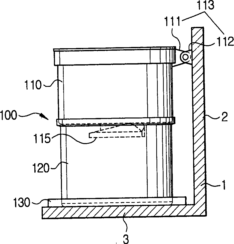
Cyclonic vacuum cleaners provide an increased volume dust container by configuring the cyclonic body of the vacuum cleaner to be pivotally mounted to the vacuum cleaner body. By rotating it about the pivot seat, the cyclone body is disconnected from the dust container by rotating or "opening" the cyclone body. The dust container removably installed in the cleaner body and the cyclone body hinged on the upper part of the cleaner body are selectively detached and connected with respect to the dust container.

Description

technical field [0001] The present invention relates to vacuum cleaners, and in particular, the present invention relates to cyclonic vacuum cleaners which separate dust from air drawn in using cyclonic dust collectors. Background technique [0002] Vacuum cleaners are known to suck in dirt and dust-laden air by suction generated by a fan or blower inside the vacuum cleaner body. Most prior art vacuum cleaners use filter bags commonly known as dust bags to separate and collect dirt and dust. When the dust bag is filled, the effectiveness of the vacuum cleaner is reduced, so that the dust bag must be emptied or replaced frequently. However, when replacing or emptying the dust bag, the user needs to dispose of the contaminated dust bag, which is uncomfortable and unsanitary for the user. [0003] In order to avoid the above-mentioned problems of prior art vacuum cleaner dust bags, cyclonic dust collectors were developed and their use became widespread. As is known, cyclonic...

Claims


Application Information

Patent Timeline
Patent Type & Authority Applications(China)
IPC IPC(8): A47L9/16A47L9/10
CPCA47L9/106A47L9/1691A47L9/16
Inventor 吴长根韩政均
Owner SAMSUNG GWANGJU ELECTRONICS CO LTD
Learn More