Omnidirectional antenna radiant unit

A radiating element, omnidirectional antenna technology, applied in the direction of resonant antenna, mid-position feeding between antenna endpoints, etc., can solve the problem of narrow antenna frequency band characteristics, inconvenient upper sidelobe suppression and lower zero filling technology, etc., to achieve the frequency band The effect of widening width, good control, and improving impedance characteristics

Inactive Publication Date: 2006-05-31
TONGYU COMM INC
View PDF0 Cites 1 Cited by
  • Summary
  • Abstract
  • Description
  • Claims
  • Application Information

AI Technical Summary

Problems solved by technology

As a result, the radiation patterns of the low-frequency and high-frequency frequencies are not in the same direction
This makes the antenna frequency band character...

Method used


Image

  • Omnidirectional antenna radiant unit
  • Omnidirectional antenna radiant unit
  • Omnidirectional antenna radiant unit

Examples


Embodiment 1

[0025] Embodiment 1: Reference Figure 4 As shown in Fig. 5, the radiating unit in this embodiment has three circular metal tubes coaxially socketed in the radial direction, wherein the innermost metal tube 1 has the longest length, and serves as the metal base tube of the radiating unit, and simultaneously serves as an antenna and an array The supporting metal tube of the antenna, the metal tube 2 sleeved on the periphery of the metal tube 1 is a radiation excitation tube, the length is about 1 / 2λ 0 , the metal pipe 3 is a parasitic pipe, which is sleeved on the periphery of the metal pipe 2, and its length is shorter than the metal pipe 2. There is an annular gap between two adjacent metal pipes, and the gap is filled by insulating medium 4 and medium 5 . The metal tubes 1, 2, 3 and the media 4, 5 together constitute the radiation unit.

[0026] The upper port 6 and the lower port 7 of the radiation unit are respectively formed between the upper and lower ends of the metal...

Embodiment 2

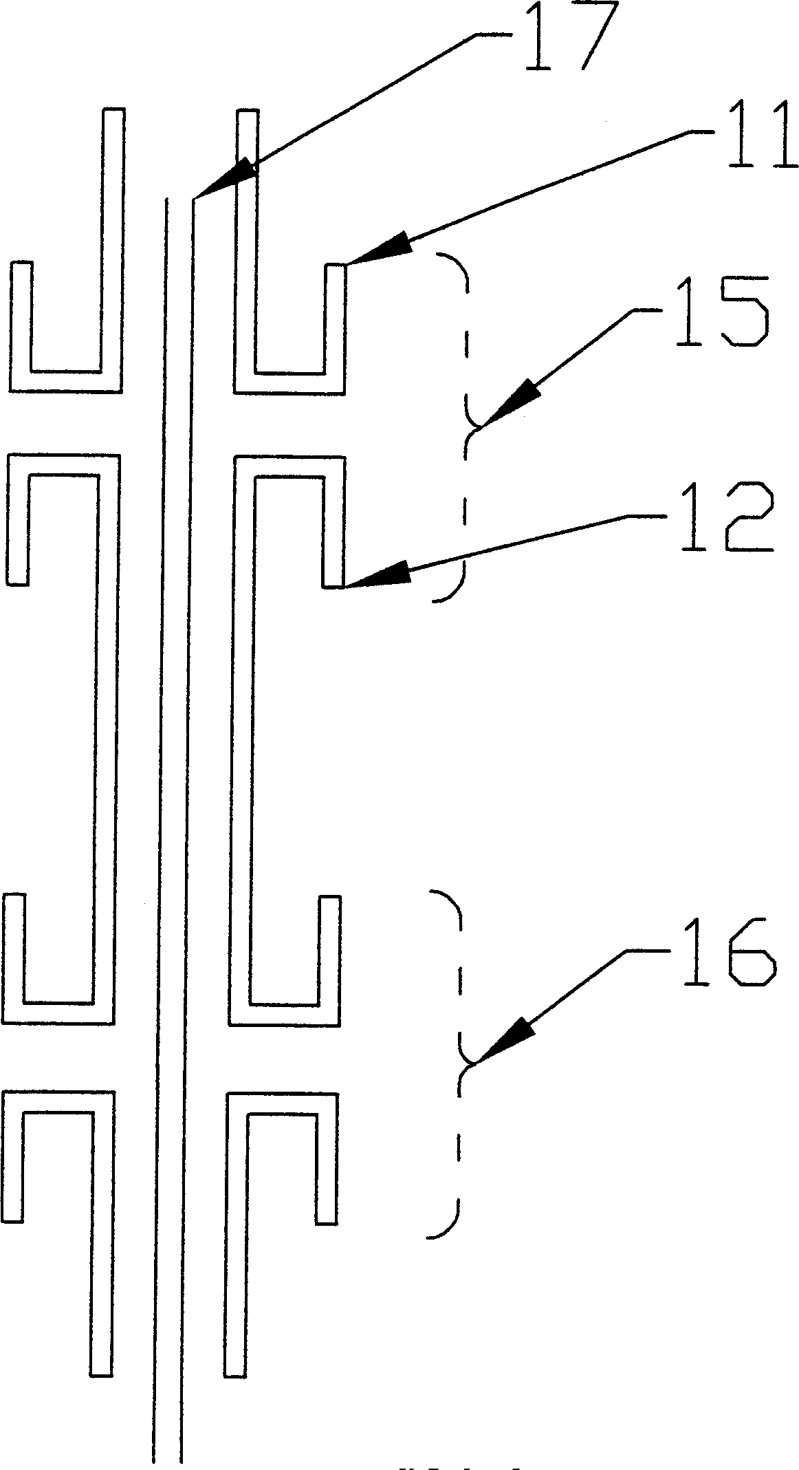
[0029] Embodiment 2: Reference Figure 6 , when in embodiment one, when the position of feed point is fed near one end or both ends of the port, zero potential is formed in the middle of the metal tube, so the metal tubes are connected together with conductors 18, as shown in the figure.

Embodiment 3

[0030] Embodiment 3: Referring to FIG. 7 , this embodiment is different from the above embodiment in that it only consists of metal pipe 1 and metal pipe 2 , but has the same characteristics as the above embodiment.


PUM


Abstract

A radiator unit for omnidirectional antenna is composed of a basic conductor tube and one or more external conductor tubes sleeving on said basic conductor tube. Its radiation terminal is the space between the end of said external tube(s) and the external surface of basic tube. The distance between two radiation terminal is 1/2 wavelength of central frequency. Its advantages are wider bandwidth and higher gain.

Description

【Technical field】 [0001] The invention relates to an omnidirectional antenna radiation unit. 【Background technique】 [0002] The omnidirectional antenna radiating element is usually a linear half-wave symmetrical oscillator. Such as figure 1 , the linear half-wave symmetric vibrator is usually composed of arms 11 and 12 of equal length, the spatial positions of the two arms are on the same straight line, and the length of each arm is generally 1 / 4λ 0 (λ 0 is the center frequency wavelength, the same below), and is fed in the middle of the vibrator. The gain of the half-wave symmetrical oscillator is 2.15dB. When the half-wave symmetrical oscillator is used to form an omnidirectional array antenna, its structure usually has two structures: parallel feed and series feed ( figure 2 and image 3 ). [0003] Such as figure 2 , is a unit for a parallel-fed antenna. A coaxial cable 13 is used to feed the vibrator in the middle of the vibrator. Due to the influence of the...

Claims


Application Information

Patent Timeline
IPC IPC(8): H01Q9/16H01Q9/20H01Q9/22H01Q9/28
Inventor 吴中林
Owner TONGYU COMM INC
Why Eureka
Try Eureka