Side plate for heat exchanger, heat exchanger, and method of manufacture heat exchanger

A technology for heat exchangers and heat exchange tubes, applied to the side plates of heat exchangers, heat exchangers and the fields of manufacturing the heat exchangers, can solve the problems of deformation of fins, unsightly appearance of heat exchangers, etc. , to avoid slippage

Inactive Publication Date: 2006-05-31
SHOWA DENKO KK
View PDF1 Cites 10 Cited by
  • Summary
  • Abstract
  • Description
  • Claims
  • Application Information

AI Technical Summary

Problems solved by technology

Even if the technique of the above publication is applied to the side plates and the corrugated fins, the fins are locally deformed, making the appearance of the heat exchanger unsightly

Method used


Image

  • Side plate for heat exchanger, heat exchanger, and method of manufacture heat exchanger
  • Side plate for heat exchanger, heat exchanger, and method of manufacture heat exchanger
  • Side plate for heat exchanger, heat exchanger, and method of manufacture heat exchanger

Examples


Embodiment Construction

[0050] Embodiments of the present invention will be described below with reference to the accompanying drawings.

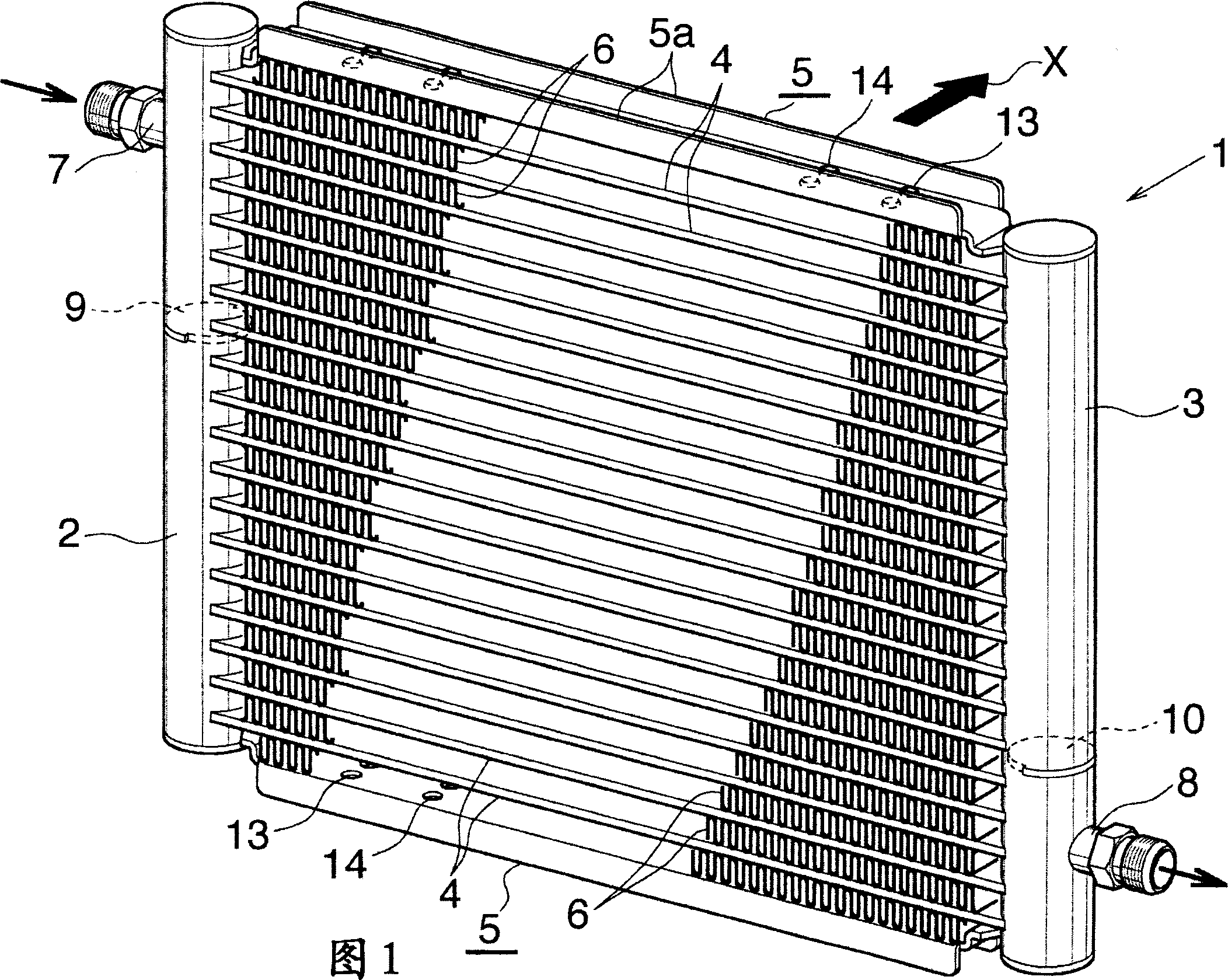
[0051] In the following description, the term "aluminum" includes aluminum alloys in addition to pure aluminum. In addition, in the following description, the upper and lower parts, left-hand side and right-hand side of Fig. 1 will be referred to as "upper", "lower", "left" and "right", respectively, and the flow direction of the air passing through the condenser The downstream side (ie, the direction indicated by arrow X in FIG. 1 ) is called "front", and the opposite side is called "rear".

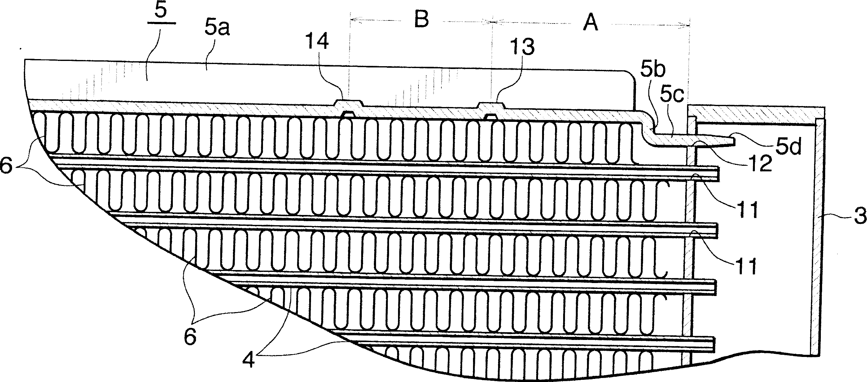
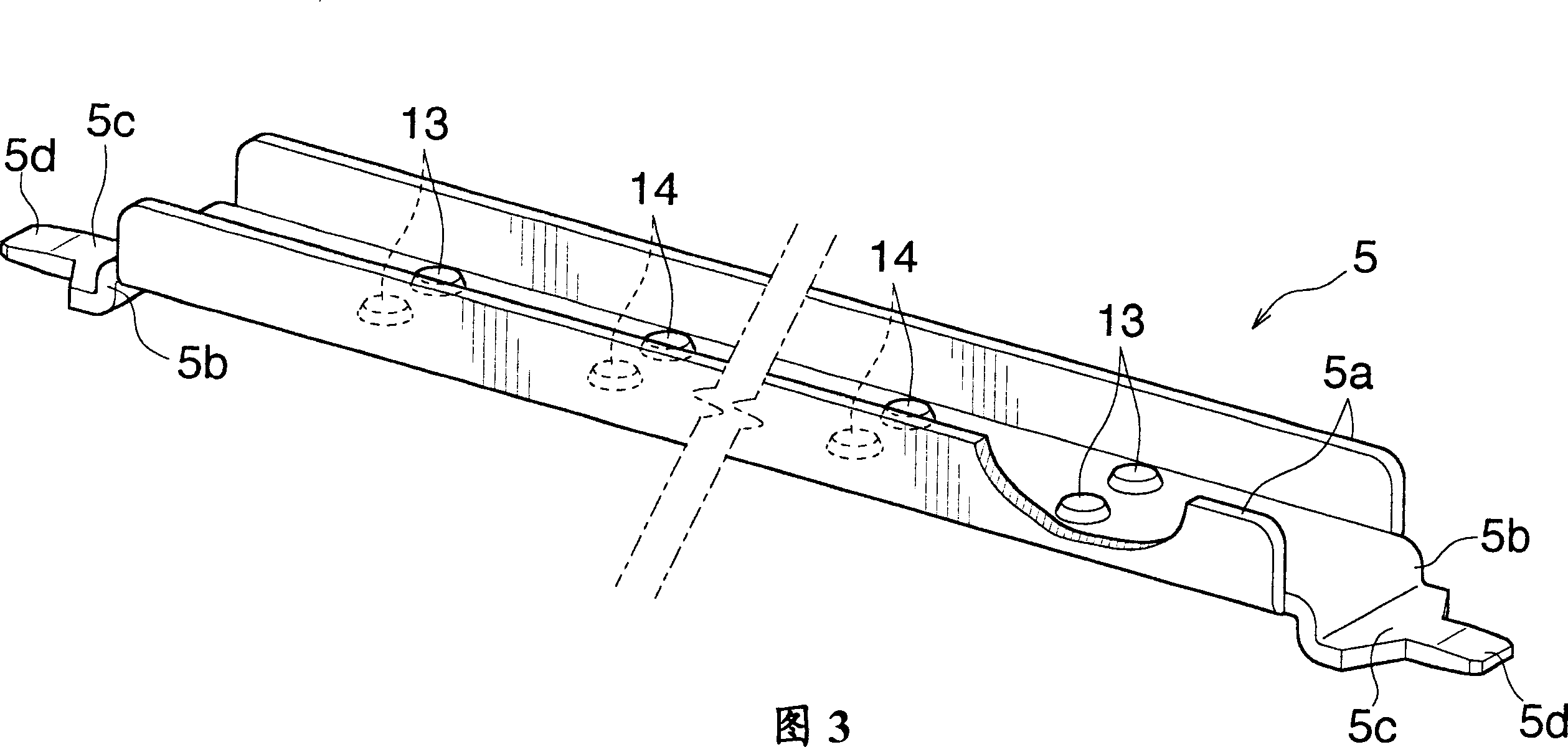
[0052] 1 and 2 show a condenser suitable for use in a motor vehicle air-conditioning system and in which a side panel according to the invention is used. Figure 3 shows the side panel. Figures 4 and 5 show a method for manufacturing the condenser.

[0053] Referring to Figures 1 and 2, the condenser 1 (heat exchanger) for motor vehicle air conditioning equipment includes ...


PUM


Abstract

The invention discloses a side plate (5) for a condenser (1), which comprises a pair of headers (2, 3) spaced apart from each other, a plurality of headers (2, 3) spaced apart from each other and arranged in parallel at the header Flat refrigerant tubes (4) between the tubes (2, 3) and both ends of which are connected to respective headers, and corrugated fins (6) arranged between adjacent refrigerant tubes (4). The side plate (5) is arranged outside and at a distance from the refrigerant tube (4) at each of the two ends of the tube arrangement. Corrugated fins (6) are provided between the side plate (5) and the end refrigerant tube (4) adjacent thereto. The side plate (5) has a protrusion (13) at each of both ends of the opposite surface of its surface in contact with the corrugated fin (6). The side plate (5) is used to prevent the fins (6) from slipping from between the refrigerant tube (4) and the side plate (5) when the condenser (1) is manufactured.

Description

[0001] Cross References to Related Applications [0002] This application is an application filed under 35 U.S.C. § 111(a) and a provisional application filed under 35 U.S.C. § 111(b) under 35 U.S.C. § 111(b) under 35 U.S.C. § 119(e)(1) Priority filing date for No. 60 / 477,775. technical field [0003] The invention relates to a side plate for a heat exchanger, a heat exchanger and a method for producing the heat exchanger. Background technique [0004] Such heat exchangers are well known: that is, the heat exchanger comprises a pair of headers spaced apart from each other, a plurality of spaced apart headers arranged in parallel between the headers and connected at both ends to the respective headers. Flat heat exchange tubes, side plates arranged outside the flat heat exchange tubes at both ends of the tube device and at a certain distance from the corresponding flat heat exchange tubes, and arranged between adjacent heat exchange tubes and each side plate and its correspo...

Claims


Application Information

Patent Timeline
Patent Type & Authority Applications(China)
IPC IPC(8): F28F9/26
Inventor 井川洋平
Owner SHOWA DENKO KK
Why Eureka
Try Eureka