Extended range RFID system

A technology of RFID tags and antenna elements, applied in the field of RFID systems, can solve problems such as limited range and achieve the effect of expanding the coupling range

Inactive Publication Date: 2006-05-31
AVERY DENNISON CORP
View PDF4 Cites 7 Cited by
  • Summary
  • Abstract
  • Description
  • Claims
  • Application Information

AI Technical Summary

Problems solved by technology

However, the disclosed device includes a central conductive region separated from the generally conductive region by a narrow peripheral slot, so the primary antenna structure is that of a relatively small slot antenna with very limited range

Method used


Image

  • Extended range RFID system
  • Extended range RFID system
  • Extended range RFID system

Examples


Embodiment Construction

[0033] Before proceeding to a detailed description of the drawings, some background information needs to be stated first. Specifically, the well-known relationship between frequency and wavelength is as follows:

[0034] L=c / F (1)

[0035] F=c / L (2)

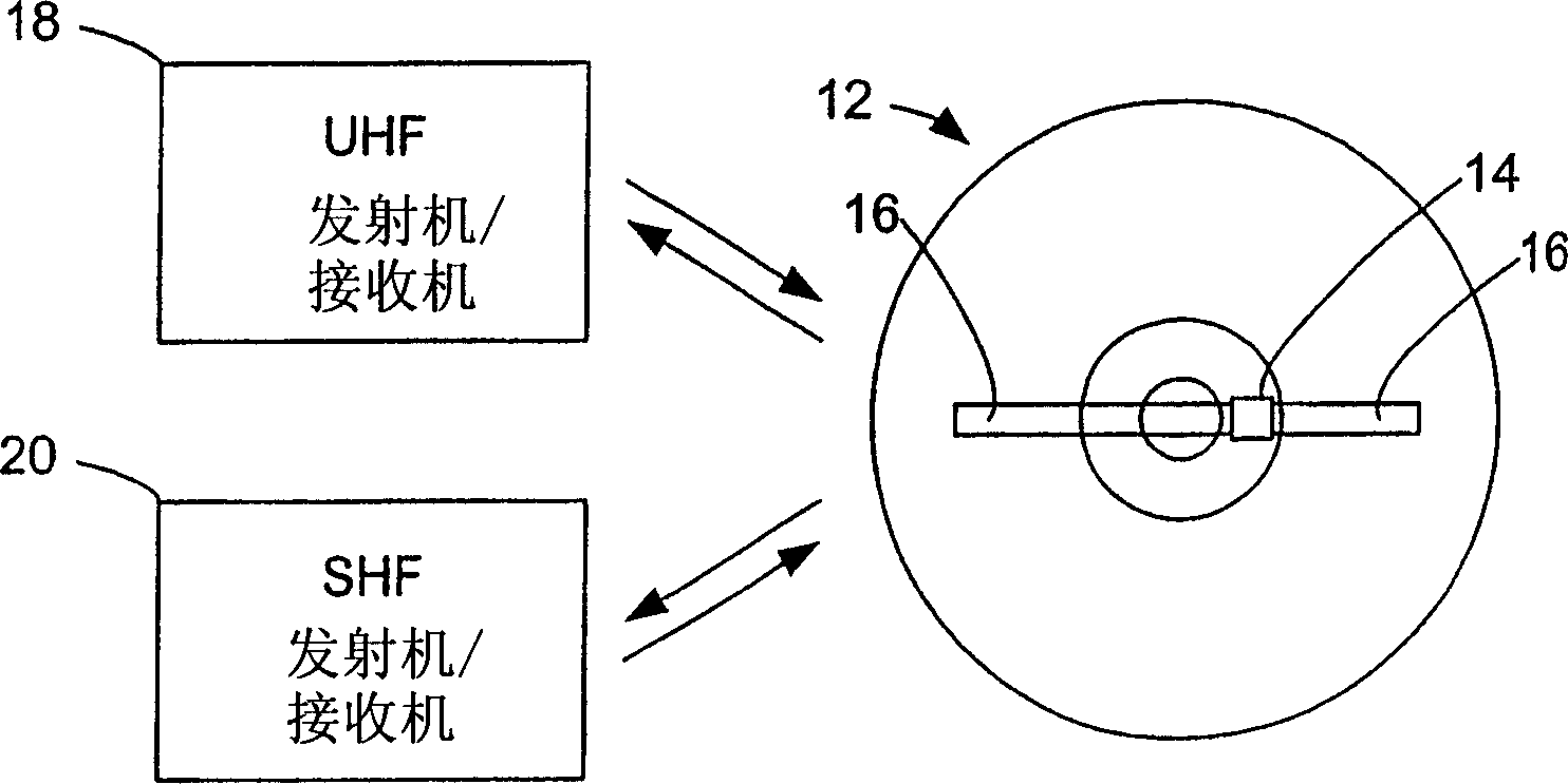
[0036]where L is the wavelength; c is the speed of light or electrical signals, equal to about 3×10 per second 10 cm; and F is the frequency. Using equation (1) given above, at a frequency of 915 MHz, the wavelength is about 32.78 centimeters (cm), and the half wavelength is about 16.4 cm. at 2.45GHz or 2.45×10 9 At Hz frequency, the wavelength is about 12.2 cm, and the half wavelength is about 6.1 cm. By the way, the frequency range from 860 to 960 MHz is commonly referred to as the UHF band, while the frequency range from 2.4 to 2.5 GHz or 2.4×10 9 to 2.5×10 9 The frequency range is often referred to as the super high frequency (SHF) band.

[0037] It should also be noted that RFID systems are generally known an...


PUM

PropertyMeasurementUnit
diameteraaaaaaaaaa

Abstract

A radio frequency identification (RFID) system for discs such as CDs, DVDs or minidiscs includes a special RFID transponder and antenna configuration. The discs normally include an outer metallized annular zone (20) where information is stored, a central hole (28), and an inner annular zone (26) between the hole and the outer annular zone. The transponder (24) may be located in the inner annular zone, with antenna elements (32, 34) coupled to the transponder extending in opposite directions part way across the outer annular zone. Multilayer labels with a recess for the transponder chip, and antenna elements formed by conductive material may be employed to apply the RFID assembly to the discs. A monopole or dipole mode of antenna operation, prominently involving the metallized disc layer, results from the antenna configuration, and serves to more than double the range of the system.

Description

technical field [0001] The present invention relates to RFID systems, in particular RFID systems for Compact Discs (CDs), Digital Versatile Discs or Digital Video Discs (DVDs), or Mini Discs. Background technique [0002] It has been proposed to use Radio Frequency Identification (RFID) transponders for CDs or DVDs, and US Patent Publication No. US2002 / 0175818 A1 discloses such a device in its Figures 18 and 19 . However, the disclosed device includes a central conductive region separated from the normal conductive region by a narrow peripheral slot, so that the primary antenna structure is that of a relatively small slot antenna with very limited range. This structure also uses a conductive sheet extending to the periphery of the optical disc or disk, but the main radiation is from the relatively small area slot antenna. Contents of the invention [0003] Therefore, one of the main objects of the present invention is to significantly increase the range of the RFID-on-dis...

Claims


Application Information

Patent Timeline
Patent Type & Authority Applications(China)
IPC IPC(8): G06K19/07G11B20/00
CPCG06K19/045G06K19/0723G06K19/07752G06K19/07786G11B20/00086G11B20/00115G11B20/00876
Inventor I·J·福斯特
Owner AVERY DENNISON CORP
Why Eureka
Try Eureka