
Suspension system for vehicle

A suspension system, vehicle technology, applied in the direction of suspension, elastic suspension, interconnection system, etc.

Inactive Publication Date: 2006-06-07
AISIN SEIKI KK
View PDF3 Cites 5 Cited by
  • Summary
  • Abstract
  • Description
  • Claims
  • Application Information

AI Technical Summary

Problems solved by technology

In the technology described in the above-mentioned patent documents, the influence of the above-mentioned transverse G is not considered, and the suspension system described in the above-mentioned patent documents still has room for improvement from a practical point of view.

Method used


Image

  • Suspension system for vehicle
  • Suspension system for vehicle
  • Suspension system for vehicle

Examples


Embodiment Construction

[0037] Hereinafter, embodiments of the present invention will be described in detail with reference to the drawings. In addition, the following examples of the present invention are only used to further describe the present invention in detail, and the scope of protection of the present invention is not limited to the forms described in the items of the above-mentioned content of the invention. Changes and implementation of various improvements.

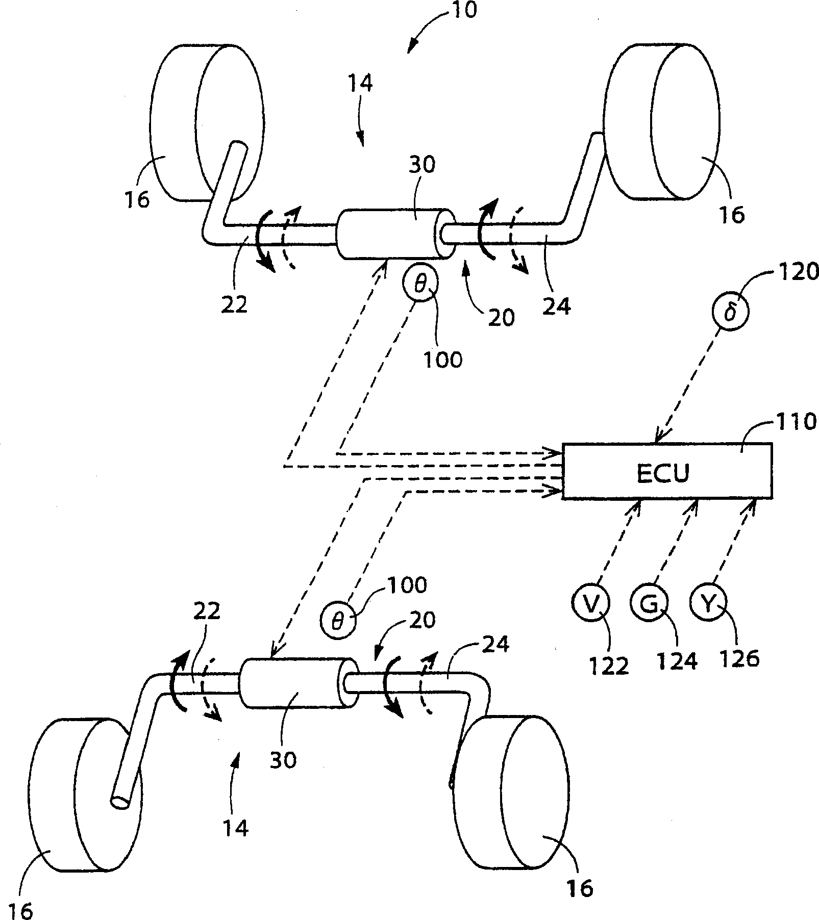
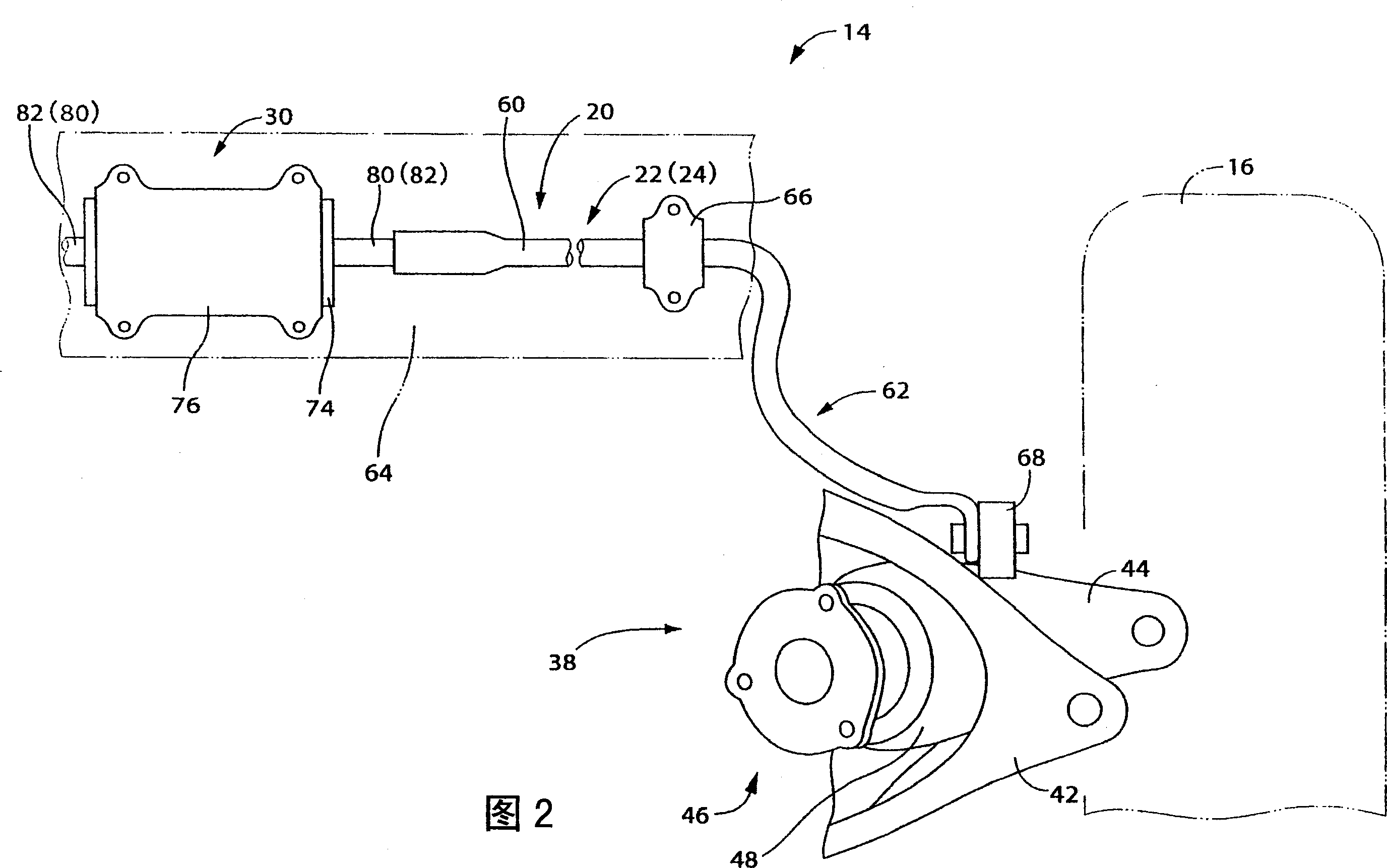
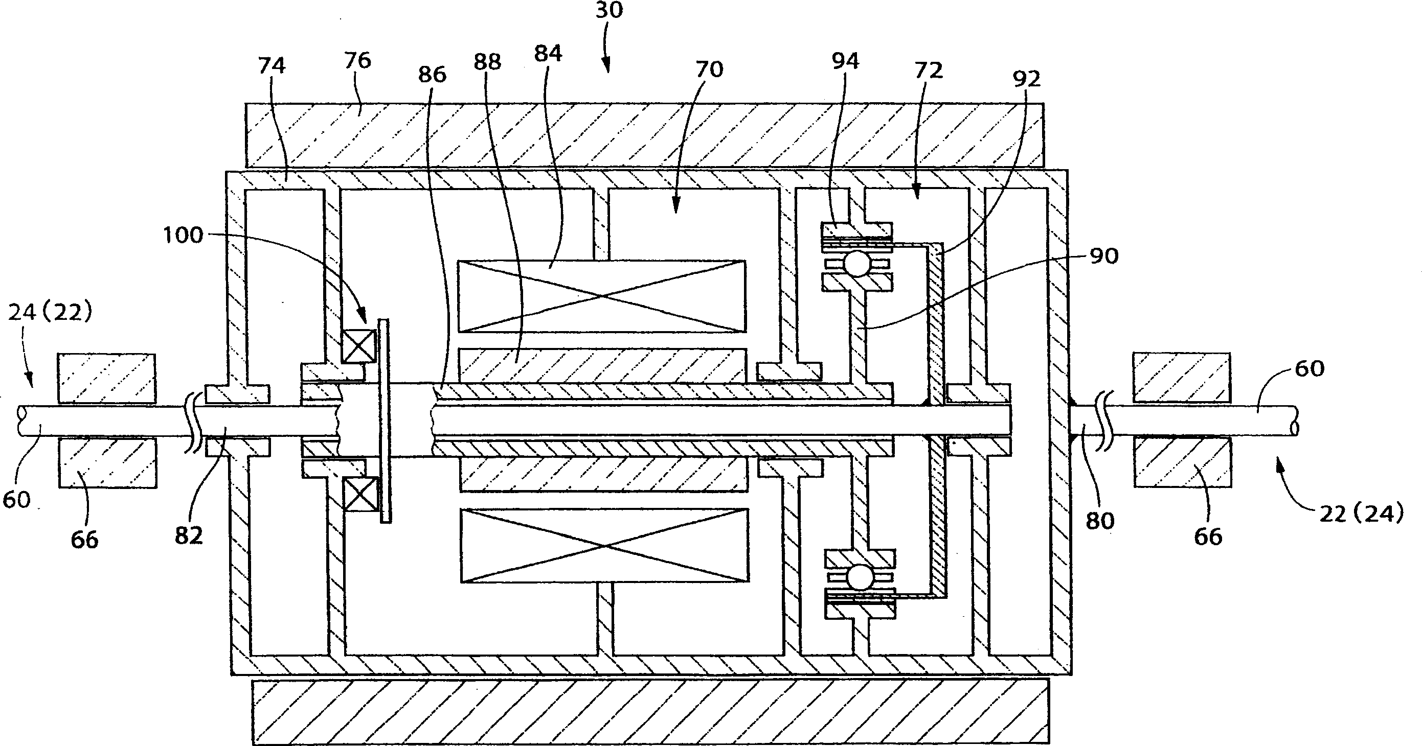
[0038] figure 1 It is a schematic diagram showing a suspension system for a vehicle as an embodiment of the present invention. The vehicle suspension system 10 is provided on the front wheel side and the rear wheel side of the vehicle, respectively, and includes two stabilizer devices 14 each functioning as a roll suppressing device. The stabilizer devices 14 each have a stabilizer bar 20 connected at both ends to a wheel holding member (see FIG. 2 ) holding the wheel 16 . The stabilizer bar 20 is divided at the center and has a str...


PUM


Abstract

The present invention discloses a suspension system for a vehicle, which has a roll suppressing device such as a stabilizer device. When determining the target rotation angle θ of the actuator of the roll suppressing device, if the actual lateral G, that is, the lateral acceleration actually generated on the vehicle body, is smaller than the first threshold Gy1 (S19), based on the estimated lateral G, that is, according to Determine the lateral acceleration obtained from the steering angle δ and the vehicle speed v (S20). If the actual lateral G is greater than the second threshold Gy2 (S21), then determine based on the actual lateral G (S18). In addition, if the actual lateral G When it is greater than or equal to the first threshold Gy1 and less than or equal to the second threshold Gy2, it is based on the difference between the value of the actual horizontal G multiplied by the coefficient α that increases linearly from 0 to 1, and the value of the estimated horizontal G multiplied by the coefficient (1-α) and determine (S22). It is thereby possible to prevent control play from occurring while excluding the influence of comparatively small lateral accelerations that are not related to the rotation of the vehicle.

Description

technical field [0001] The present invention relates to a suspension system for a vehicle, and in particular to control of the roll suppression device of a suspension system having a roll suppression device for controlling the roll of a vehicle body. Background technique [0002] Regarding control of a suspension system having a roll suppressing device, there are techniques described in the following patent documents. In each of these techniques, the control value of the roll control device is determined using actual lateral acceleration (hereinafter sometimes simply referred to as "actual lateral G") and estimated lateral acceleration (hereinafter sometimes simply referred to as "estimated lateral G"). The actual lateral acceleration is the actual lateral acceleration generated in the vehicle body, and the estimated lateral acceleration is estimated based on the vehicle traveling speed and the steering amount. [0003] Patent Document 1: JP-A-5-50819. [0004] Patent Docu...

Claims


Application Information

Patent Timeline
Patent Type & Authority Applications(China)
IPC IPC(8): B60G17/016
CPCB60G17/0182B60G17/01908B60G21/0553B60G2400/104B60G2202/42B60G2202/442B60G2204/419
Inventor 山田大介松本伸浦马场真吾铃木聪
Owner AISIN SEIKI KK
Learn More