New type air sterilization device

An air sterilizer, a new type of technology, applied in the direction of disinfection, deodorization, etc., can solve the problems of inability to control viruses and germs, and inability to achieve direct air disinfection.

Inactive Publication Date: 2006-07-05
方墨希
View PDF0 Cites 7 Cited by
  • Summary
  • Abstract
  • Description
  • Claims
  • Application Information

AI Technical Summary

Problems solved by technology

These methods can only sterilize the polluted site, but cannot control the viruses and germs brought in when people re-enter the site, let alone control the viruses and germs that drift with the air due to ventilation. The purpose of direct disinfection

Method used


Image

  • New type air sterilization device
  • New type air sterilization device
  • New type air sterilization device

Examples


Embodiment Construction

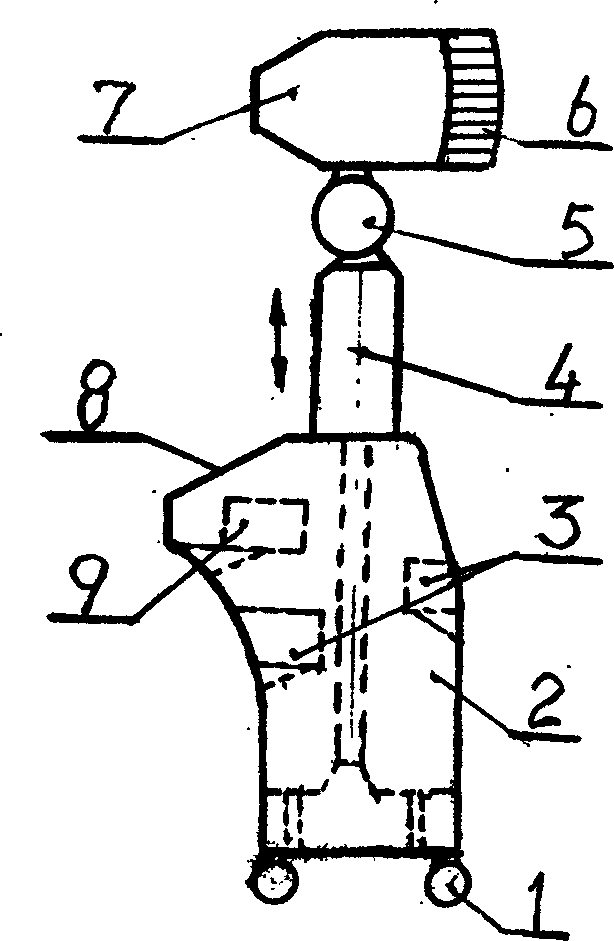
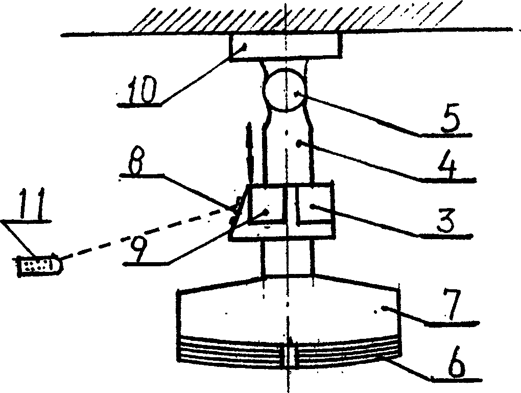
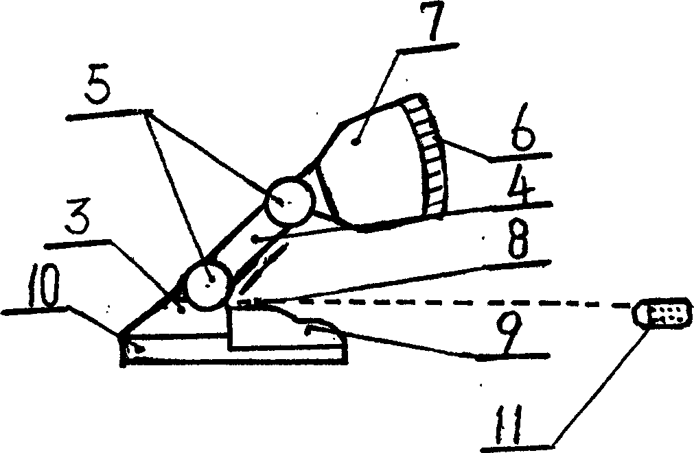
[0015] Such as figure 1 Shown: It is a floor type air sterilizer. It consists of base 1 with movable casters, box 2, power supply 3, control device 9, liftable support arm 4, rotating device 5, arc window and ultra-micro electron emitter 6, head box 7, control Panel 8 composition. Head box 7 is equipped with the circuit that links to each other with power supply 3 and control device 9. Wherein, there is a control device 9 on the power supply 3 device inside the box body 2, and the control device 9 is connected to the control panel 8. There is a base 1 with movable casters under the box body 2, and a liftable support arm 4 is arranged on the box body 2. , the support arm 4 is connected with the rotating device 5, the head casing 7 is arranged above the rotating device 5, and the ultra-micro electron emitter 6 connected with the arc window is arranged in the head casing 7; the above-mentioned device can be to 50M 3 -80M 3 Disinfect the space for disinfection.

[0016] This ...


PUM


Abstract

An air disinfector for disinfecting the air in the space from 30 or 50 cu.m to 80 or 100 cu.m by the negatively charged nanoparticles with the density of 10 to the power 4-8 per cu.m is composed of ultramicro electron-emitting electrodes, controller, power supply, arc emitting window, casing for head unit, supporting lift arm, rotary unit, and supporting frame or casing. Its advantages are no damage to operator and enxironment and high effect.

Description

Technical field: [0001] The present invention relates to a disinfection machine, in particular to a new air disinfection method that applies negatively charged nanoparticles to a new air disinfection method, completely overcomes the problems existing in existing disinfection methods, and produces a A new type of air sterilizer. Background technique: [0002] The current physical disinfection methods (such as filtration, adsorption, ozone, ultraviolet light, etc.) and chemical disinfection methods for ambient air adopted in the world must not allow people to move freely or work on site. These methods can only sterilize the polluted site, but cannot control the viruses and germs brought in when people re-enter the site, let alone control the viruses and germs that drift with the air due to ventilation. For direct disinfection purposes. For this reason, it is urgent to research and produce a kind of air disinfection device that directly disinfects the air in the working envir...

Claims


Application Information

Patent Timeline
Patent Type & Authority Applications(China)
IPC IPC(8): A61L9/16A61L9/00
Inventor 方墨希
Owner 方墨希
Why Eureka
Try Eureka