
Plate-like holding structure and electronic timepiece having the same

A timepiece and plate-shaped technology, applied in the field of electronic timepieces, can solve the problems that the main part of the plate-shaped holding structure occupies a large area and the size is easy to increase.

Inactive Publication Date: 2006-07-05
SEIKO INSTR INC
View PDF3 Cites 0 Cited by
  • Summary
  • Abstract
  • Description
  • Claims
  • Application Information

AI Technical Summary

Problems solved by technology

[0003] However, according to the plate-shaped holding structure of JP-A-2000-81491, various parts are constituted by branching and extending from the main body part, therefore, the spring part for supporting the main body of the quartz oscillator and the spring part of the positive terminal part of the battery need Spring forces are set independently of each other and are easily increased in size to provide sufficient spring force
In addition, in the case of an analog type electronic timepiece, the main body portion of the plate-shaped holding structure extends substantially over the entire timepiece body including the gear train mechanism at its central portion and parallel to the main face of the timepiece body, so it is difficult to avoid The problem that the main part of the plate-like holding structure occupies a large area

Method used


Image

  • Plate-like holding structure and electronic timepiece having the same
  • Plate-like holding structure and electronic timepiece having the same
  • Plate-like holding structure and electronic timepiece having the same

Examples


Embodiment Construction

[0023] Next, preferred embodiments of the present invention will be described based on preferred embodiments shown in the accompanying drawings.

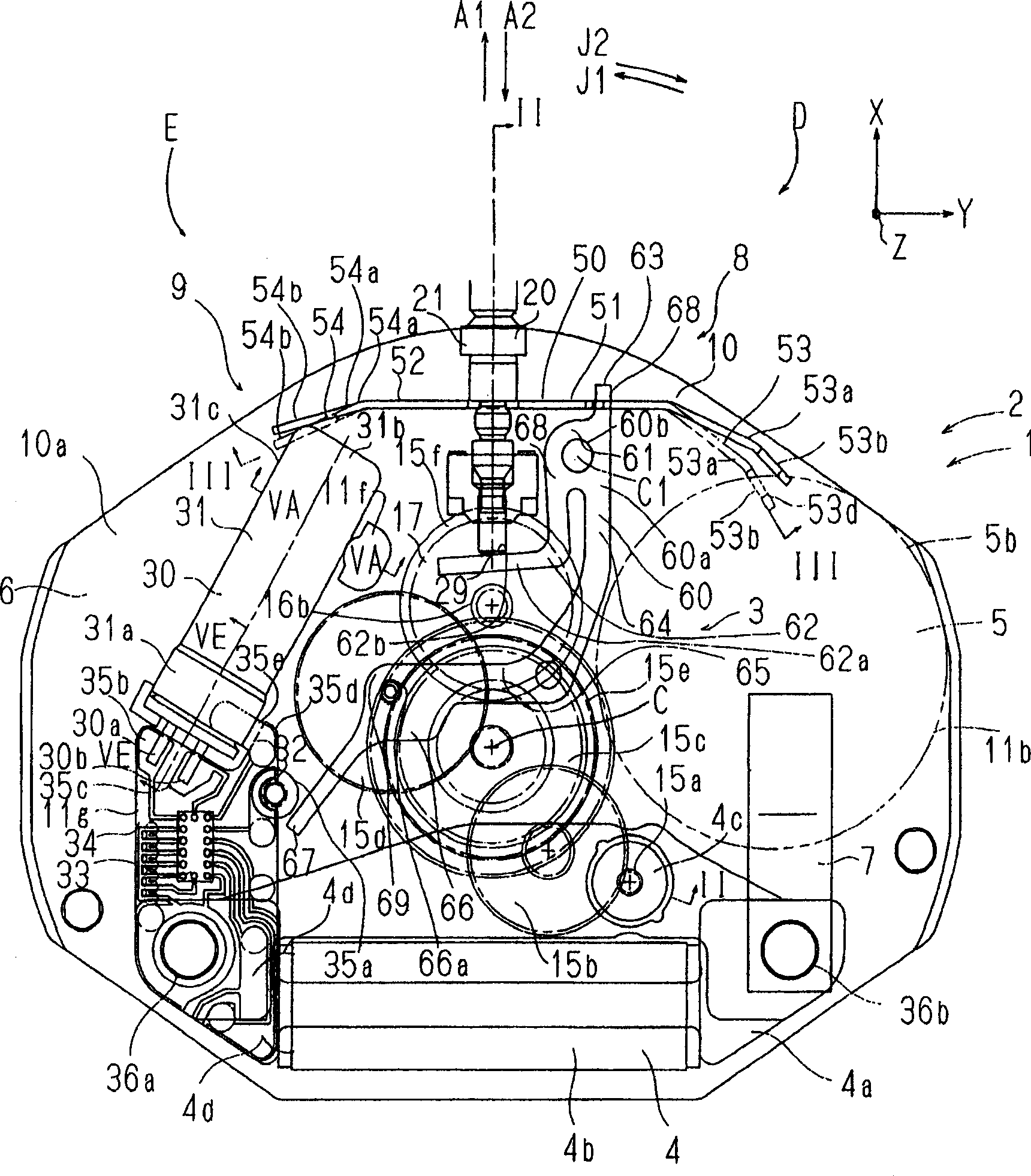
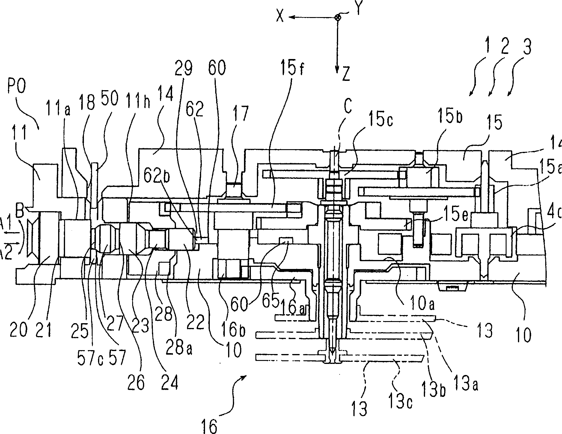
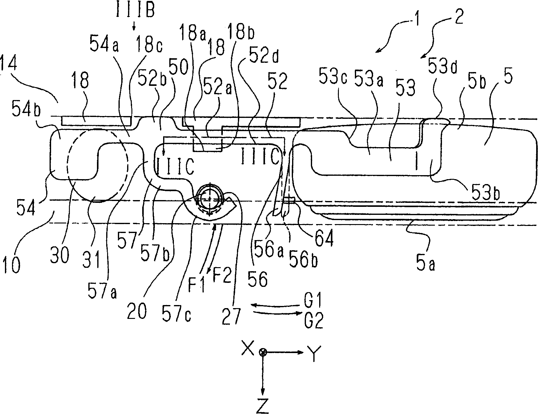
[0024] The timepiece body 2 of the electronic timepiece 1 is provided with a main plate 10 constituting a chassis. In the following, to simplify the description, a three-dimensional coordinate system fixed on the main splint 10 will be used. Here, the X direction is composed of the direction A1 in which the winding stem 20 is pulled out (3 o'clock side), and the Y direction is composed of figure 1 The right direction of is constituted (12 o'clock side) and the Z direction is constituted by the depth direction of the drawing perpendicular to the drawing. The Z direction coincides with the side with the dial 12 (refer to figure 2 ). Here, the XY plane is parallel to the principal surface of the timepiece body 2 , and the Z-axis direction is a direction perpendicular to the principal surface of the timepiece body 2 . exist figure...


PUM


Abstract

To provide a plate-like holding structure capable of fixing both of an oscillator cabinet and a battery by a minimum size and an electronic timepiece having the same. A plate-like holding structure of an electronic timepiece is a holding structure constituted by a slender leaf spring as a whole mounted to a machine frame of a timepiece main body to be substantially orthogonal to a main face of the timepiece main body and to be extended along a direction of extending the main face, including a battery holding portion brought into press contact with a battery at one end portion thereof and including an oscillator cabinet holding portion brought into press contact with a cabinet of an oscillator at other end portion thereof and constituted such that a middle portion of the two holding portions is supported by a fulcrum portion supported by the machine frame main body.

Description

technical field [0001] The present invention relates to a plate-shaped holding structure for holding an oscillator case and a battery of a timepiece, and an electronic timepiece having the plate-shaped holding structure. Background technique [0002] In electronic timepieces, a configuration is proposed in which a plate-shaped holding structure including a main body extending parallel to the main face of the timepiece main body and made of metal is fixed to the main body by thermal caulking, pins, and screws. The body portion or housing of the quartz oscillator is pressed against the main plate so as to be fixed on the quartz oscillator body support spring portion extending from the body portion, and the battery positive terminal portion extending by being bent at a right angle with respect to the body portion is pressed against On the peripheral surface of the positive electrode of the battery (JP-A-2000-81491 and JP-A-11-44774). This battery positive terminal more or less...

Claims


Application Information

Patent Timeline
Patent Type & Authority Applications(China)
IPC IPC(8): G04C10/00
CPCG04C3/008G04G19/00G04C10/00
Inventor 芳贺太一
Owner SEIKO INSTR INC
Learn More