Spot welding method, spot welding machine and spot welding robot

A technology of spot welding equipment and robots, which is applied in welding equipment, resistance welding equipment, metal processing equipment, etc., can solve the problems of resistance change, inability to accurately determine, and change of conductive area, and achieve the effect of improving reliability

Inactive Publication Date: 2006-07-05
YASKAWA DENKI KK
View PDF2 Cites 17 Cited by
  • Summary
  • Abstract
  • Description
  • Claims
  • Application Information

AI Technical Summary

Problems solved by technology

[0007] However, the method using the resistance between electrodes has the problem that the conductive area changes due to wear of the electrodes, and thus the resistance in the thickness direction of the plate changes, making accurate determination impossible.

Method used


Image

  • Spot welding method, spot welding machine and spot welding robot

Examples


Embodiment 1

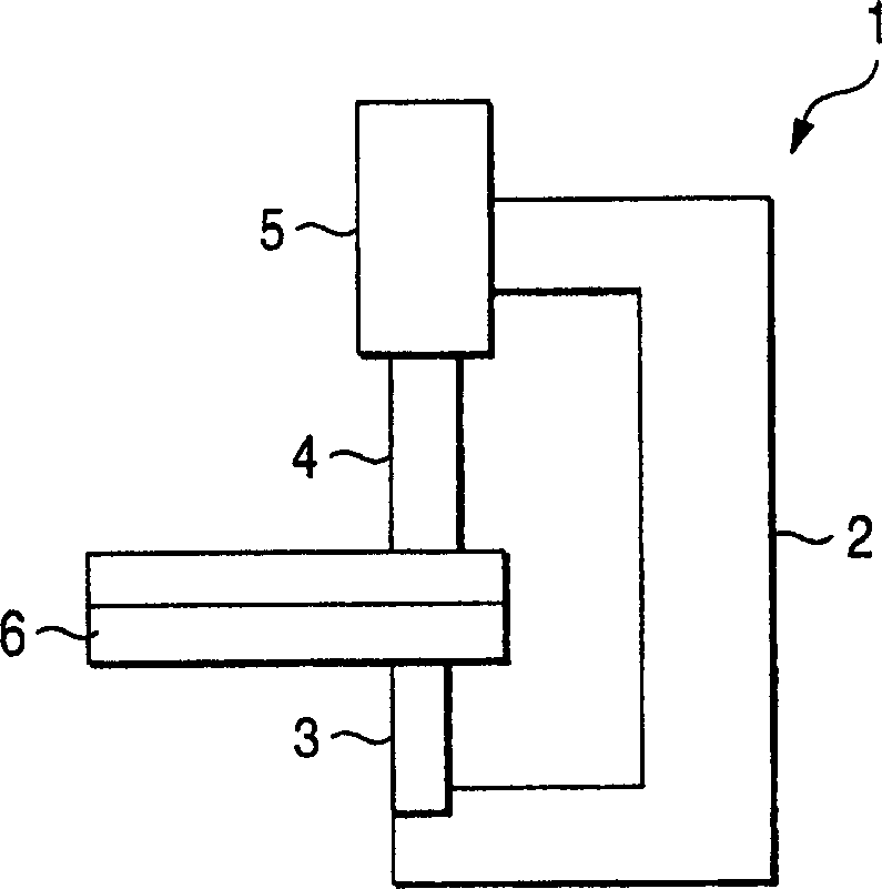
[0021] figure 1 is a conceptual diagram of a spot welding gun and shows an embodiment of the present invention. In this drawing, reference numeral 1 denotes a spot welding gun. The spot welding gun 1 is integrally equipped with an unshown transformer, and is mounted on the front end of an unshown robot to move the spot welding gun 1 to a position programmed in a control device of the aforementioned robot, thereby performing spot welding.

[0022] Reference numeral 2 denotes a frame of the spot welding gun 1, and a fixed electrode 3 is mounted on the lower part of the frame, and a movable electrode 4 is mounted on the upper part. The movable electrode 4 is driven by a servo motor 5 to move it up and down to clamp and press a workpiece 6 between itself and the fixed electrode 3 . By the above-mentioned control device of the above-mentioned robot, the servo motor 5 is controlled as an additional axis of the robot, so that the position, speed, and thrust (or pressure) of the mov...


PUM


Abstract

A spot welding machine able to positively detect a defect in a work and defects such as caught-in freign matters. A spot welding method which holds and pressurizes stacked works (6) between a fixed electrode (3) and a movable electrode (4) and supplies a current to between the fixed electrode (3) and the movable electrode (4) to complete welding, and which comprises the step of measuring the position of the movable electrode (4) when the works (6) are held between the fixed electrode (3) and the movable electrode (4) and storing the value as a reference value TH prior to an actual welding job, the step of measuring the position TR of the movable electrode (4) when the works (6) are held between the fixed electrode (3) and the movableelectrode (4) when an actual welding is performed, and the step of comparing the position TR with the reference value TH, and performing a welding job when the position TR falls within a spcified range of the reference value TH and issuing an alarm and suspening a welding job when the position TR is outside the spcified range.

Description

technical field [0001] The present invention relates to a spot welding method and apparatus for welding superimposed workpieces by clamping and pressing them between a pair of electrodes and inputting electric energy between the electrodes, and more particularly, to a A method and device for automatically detecting the absence of a workpiece or the clamping of a foreign object. Background technique [0002] Spot welding of superimposed workpieces by clamping and pressing them between a pair of electrodes and inputting electric energy between the electrodes is often used in the field of assembling chassis of automobiles or the like. Especially in recent years, spot welding equipment and spot welding robots that automatically perform spot welding by installing an electronic spot welding gun (the electrode of which is driven and pressed by a servo motor) on an industrial robot instead of a pneumatic device have been widely popularized. [0003] In an automatic production line ...

Claims


Application Information

Patent Timeline
Patent Type & Authority Applications(China)
IPC IPC(8): B23K11/24B23K11/25
CPCB23K11/253B23K11/24B23K11/25
Inventor 中村正夫
Owner YASKAWA DENKI KK
Why Eureka
Try Eureka