Plasma display screen fault checking method

A technology of a plasma display screen and an inspection method, which is applied in the direction of measurement/testing in the manufacturing process, and can solve problems such as inability to perform inspection

Inactive Publication Date: 2006-07-12
四川世纪双虹显示器件份有限公司
View PDF0 Cites 19 Cited by
  • Summary
  • Abstract
  • Description
  • Claims
  • Application Information

AI Technical Summary

Problems solved by technology

[0003] At present, the electrodes of the plasma display screen include the electrode part and the lead part. The traditional detection method can only be used to detect the pattern defect in the pattern area with periodic arrangement, but for the pattern area without periodic arrangement, such as the lead part appears graphic defect, namely the attached figure 1 The defect of point A in , cannot be inspected by this inspection method

Method used


Image

  • Plasma display screen fault checking method
  • Plasma display screen fault checking method
  • Plasma display screen fault checking method

Examples


Embodiment Construction

[0016] The method described in the present invention will be further described below in conjunction with the accompanying drawings and the embodiments provided by the inventor.

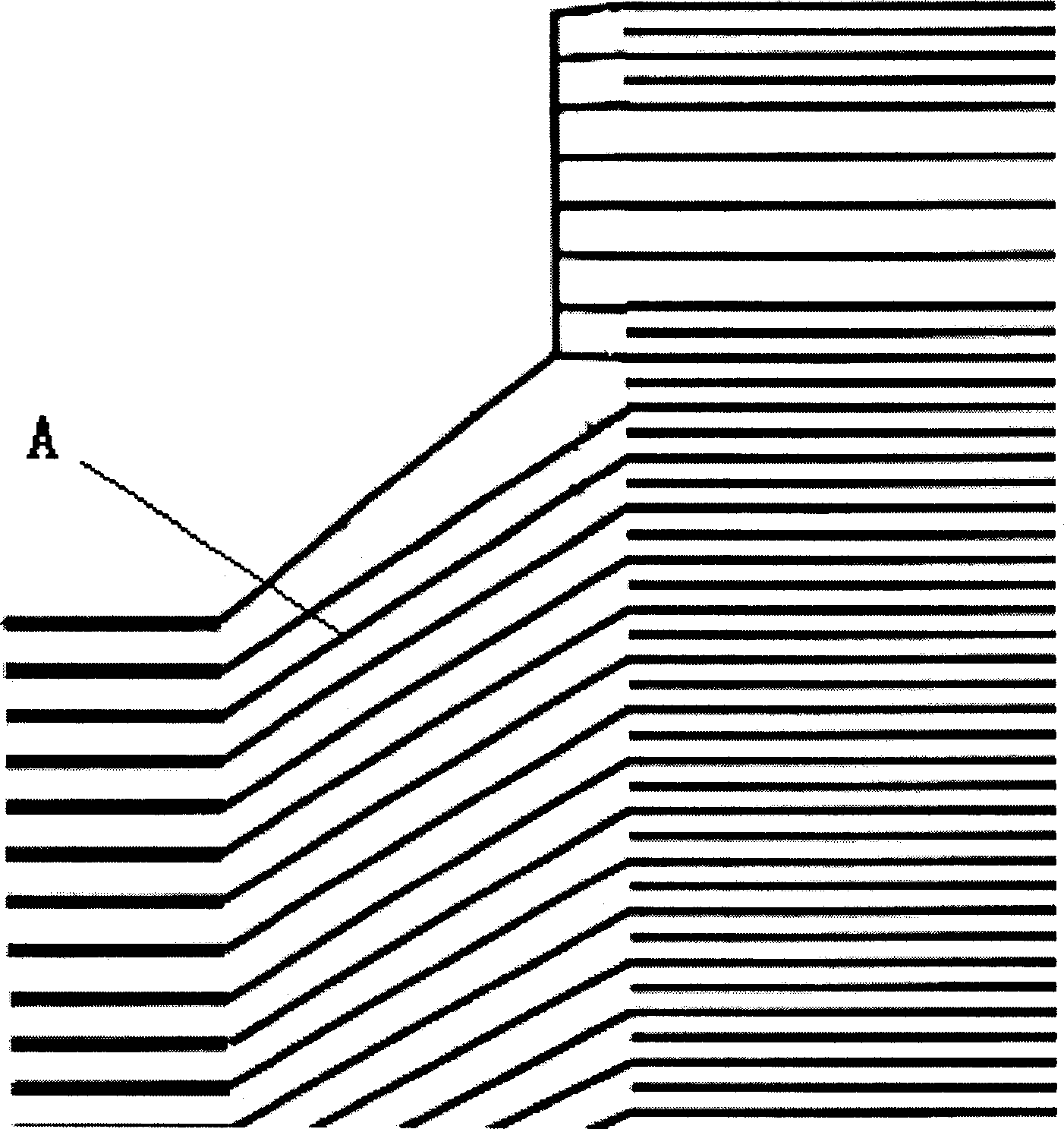
[0017] Taking the inspection of the bus electrode of the substrate on the 60-inch plasma display as an example to further illustrate this inspection method.

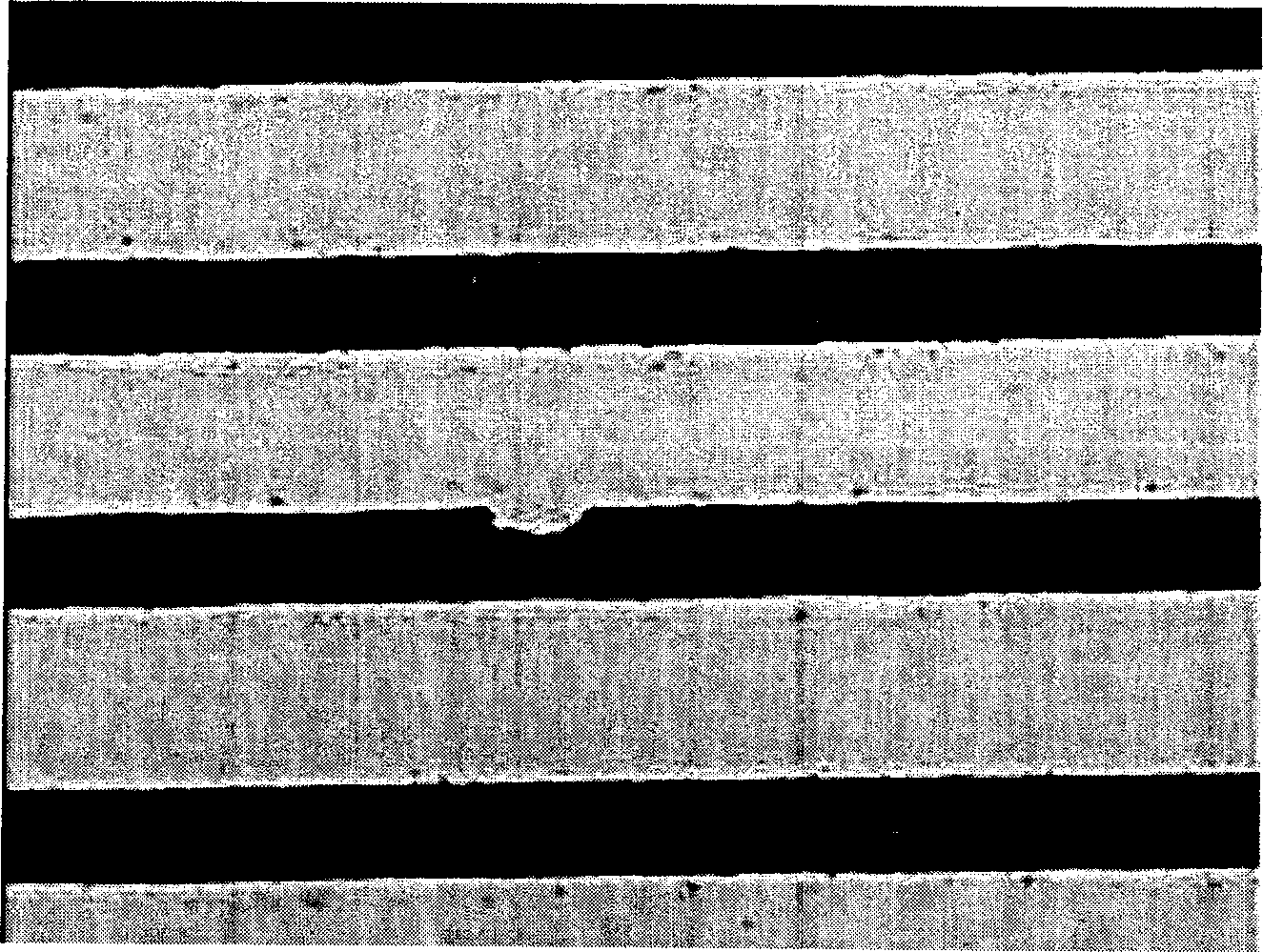
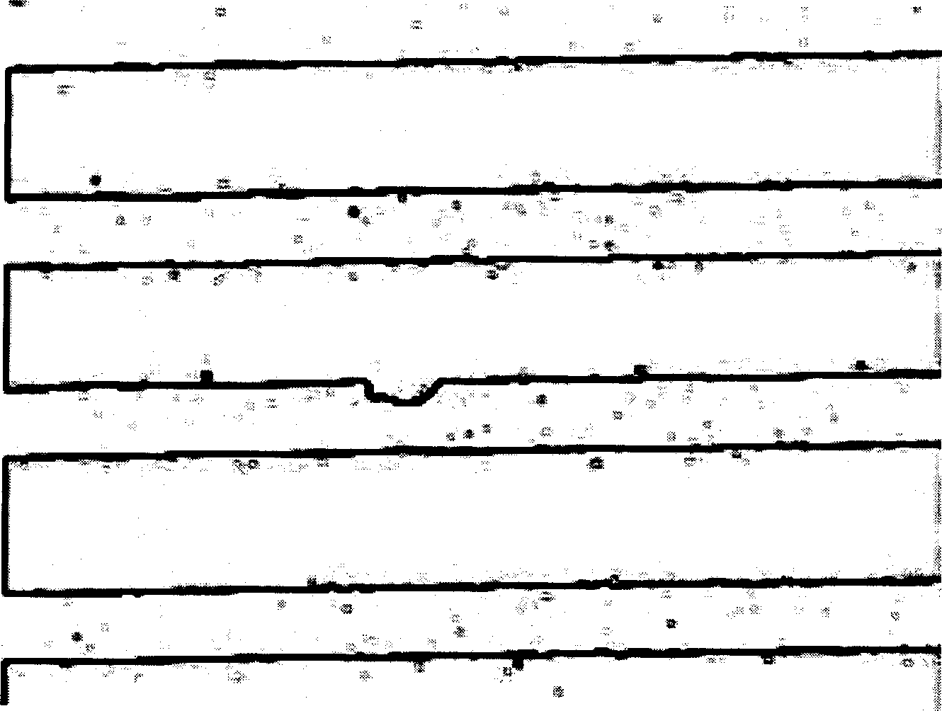
[0018] First use CCD camera to shoot figure 1 A surface image of a portion of the bus electrodes of the plasma display shown. The principle of controlling the brightness of the lighting source during shooting is that the bus electrode lines can be clearly seen on the captured image, and the gray value of the line part and the glass substrate without the line is obviously different, which is convenient for thresholding processing in the later stage. The entire surface of the substrate is evenly illuminated. In this example, segmented brightness-controllable high-frequency fluorescent tubes are used as the lighting source.

[0019] After the su...


PUM


Abstract

The method to detect plasma display screen defect comprises: obtaining the screen surface image with high-resolution camera for threshold treatment; taking differential minus treatment to the treated image with preset standard image; detecting defect point according to detection condition. This invention needs no repeated calculation, and also fit to nonperiodic image.

Description

technical field [0001] The invention relates to a method for inspecting defects of a plasma display screen, which is used for inspecting graphic defects occurring in the production process of the plasma display screen. Background technique [0002] As a traditional method for inspecting image defects of a display panel, a CCD camera is usually used to obtain graphic images of the substrate surface. If there is a graphic defect somewhere on the substrate, that is, an electrode disconnection or a short circuit between adjacent electrodes, the gray value of the fault point will be different from the gray value of the adjacent normal point. Defect points can be detected by periodic comparison and gray value difference of adjacent points. [0003] At present, the electrodes of the plasma display screen include the electrode part and the lead part. The traditional detection method can only be used to detect the pattern defect in the pattern area with periodic arrangement, but for...

Claims


Application Information

Patent Timeline
Patent Type & Authority Applications(China)
IPC IPC(8): H01J9/42
Inventor 陈超
Owner 四川世纪双虹显示器件份有限公司
Why Eureka
Try Eureka