

Device and method for obtaining air from water
An air and decompression device technology, applied in separation methods, chemical instruments and methods, liquid degassing, etc., can solve the problems of bulky submarines and divers, and the limitation of underwater operation time of oxygen cylinder divers, so as to save costs and avoid dangers. Effect
- Summary
- Abstract
- Description
- Claims
- Application Information
AI Technical Summary
Problems solved by technology
Method used
Image

Examples
specific Embodiment approach 1
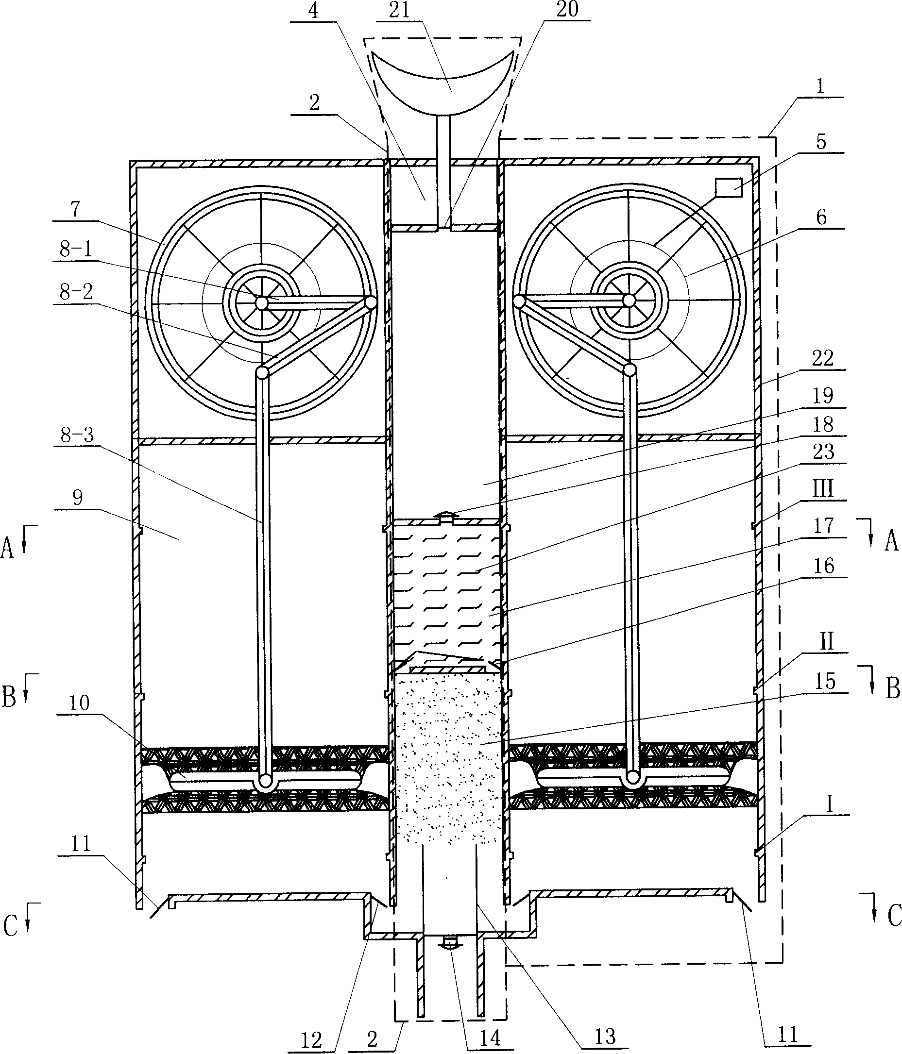
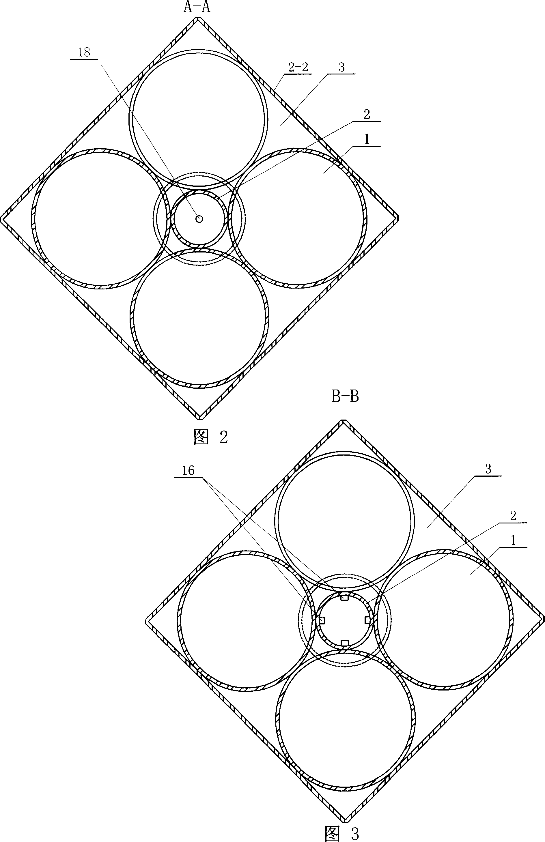
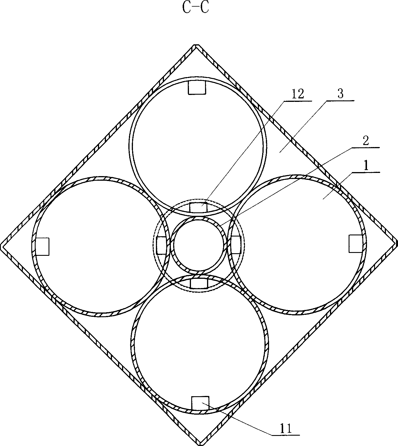
[0013] Embodiment 1: The device for obtaining air from water in this embodiment is composed of a decompression device 1, a gas collection and storage discharge device 2 and a valve control mechanism 3. The decompression device 1 can adopt N according to the amount of gas required, reducing the pressure. The pressure device 1 is connected with the gas collection, storage and discharge device 2 through the one-way valve 12 of the gas-water separation chamber, and the valve control mechanism 3 is arranged between the housing 22 and the decompression device 1 (see FIG. 2 ). The valve control mechanism 3 adopts an electromagnetic The valves are respectively connected with the one-way valve 11 of the water inlet and the one-way valve 12 of the air-water separation chamber, and the one-way valve 11 of the water inlet and the one-way valve 12 of the air-water separation chamber adopt a one-way stroke switch.
specific Embodiment approach 2
[0014] Specific embodiment two: the decompression device 1 of the present embodiment is composed of a power supply 5, a motor 6, a crank connecting rod runner mechanism 7, a connecting rod 8, a main reaction chamber 9, a piston 10 and a water inlet one-way valve 11, reducing Compression device 1 adopts four (see Fig. 2), and the output shaft of the motor 6 that is arranged on decompression device 1 top is connected with the input shaft of crank link runner mechanism 7, and the output shaft of crank link runner mechanism 7 It is connected with one end of the first connecting rod 8-1, the other end of the first connecting rod 8-1 is connected with one end of the second connecting rod 8-2, and the other end of the second connecting rod 8-2 is connected with the third connecting rod 8 The upper end of -3 is connected, the lower end of the third connecting rod 8-3 is connected with the piston 10 in the main reaction chamber 9, and the main reaction chamber 9 is at the bottom of the ...
specific Embodiment approach 3
[0015] Specific embodiment three: the gas collection and storage discharge device 2 of this embodiment (see figure 1 ) comprises baffle plate 13, one-way drain valve 14, gas-water separation chamber 15, intake one-way valve 16, gas purification chamber 17, gas storage chamber intake one-way valve 18, gas storage chamber 19, gas outlet valve 20 and The respirator 21 is provided with an air-water separation chamber 15 at the bottom of the gas collection, storage and discharge device 2, the bottom of the air-water separation chamber 15 is provided with a baffle plate 13 and a one-way drain valve 14, and the upper top of the air-water separation chamber 15 is provided with There is an air intake one-way valve 16, and a gas purification chamber 17 is arranged above the air intake one-way valve 16, and a polymer active material 23 is built in the gas purification chamber 17, and a gas storage chamber intake air is provided on the upper top of the gas purification chamber 17. One-way...
PUM
| Property | Measurement | Unit |
|---|---|---|
| height | aaaaa | aaaaa |
| diameter | aaaaa | aaaaa |
| volume | aaaaa | aaaaa |
Abstract
Description
Claims
Application Information