
DC adaptor and electronic apparatus using the same

A technology for electronic equipment and adapters, applied in the direction of converting DC power input to DC power output, instruments, circuits, etc., can solve problems such as inability to accommodate, electronic equipment not working, and inability to ensure the safety of electronic equipment

Inactive Publication Date: 2006-07-19
SONY CORP
View PDF1 Cites 4 Cited by
  • Summary
  • Abstract
  • Description
  • Claims
  • Application Information

AI Technical Summary

Problems solved by technology

[0009] In a DC adapter that can be accommodated in a general-purpose battery housing interchangeably with a primary battery and a secondary battery, the electrode terminals formed on the DC adapter also determine the polarity in the same way as the primary battery or the secondary battery. Therefore, Sometimes when the wrong polarity is inserted into the battery housing, the electronic device does not work, or it becomes the cause of a malfunction in the operation
In addition, although it is conceivable to make the shape of the DC adapter asymmetrical to the left and right, and to configure the battery housing part corresponding to the shape of the DC adapter, so as to prevent misinstallation, when storing a symmetrical primary battery or secondary battery or arranging a plurality of secondary batteries When the battery pack is used, it cannot be stored stably in the battery housing
In addition, when the terminals on the side of the battery housing part that are in contact with the electrodes of the DC adapter are used in common with the electrodes of the primary battery or secondary battery, when used for equipment other than electronic equipment that can use the DC adapter, due to the direct current The operating voltage of the adapter is different from that of the primary battery or secondary battery, which sometimes cannot ensure the safety of electronic equipment

Method used


Image

  • DC adaptor and electronic apparatus using the same
  • DC adaptor and electronic apparatus using the same
  • DC adaptor and electronic apparatus using the same

Examples


Embodiment Construction

[0035] A digital still camera as an embodiment to which the DC adapter and electronic equipment of the present invention are applied will be described in detail below with reference to the accompanying drawings.

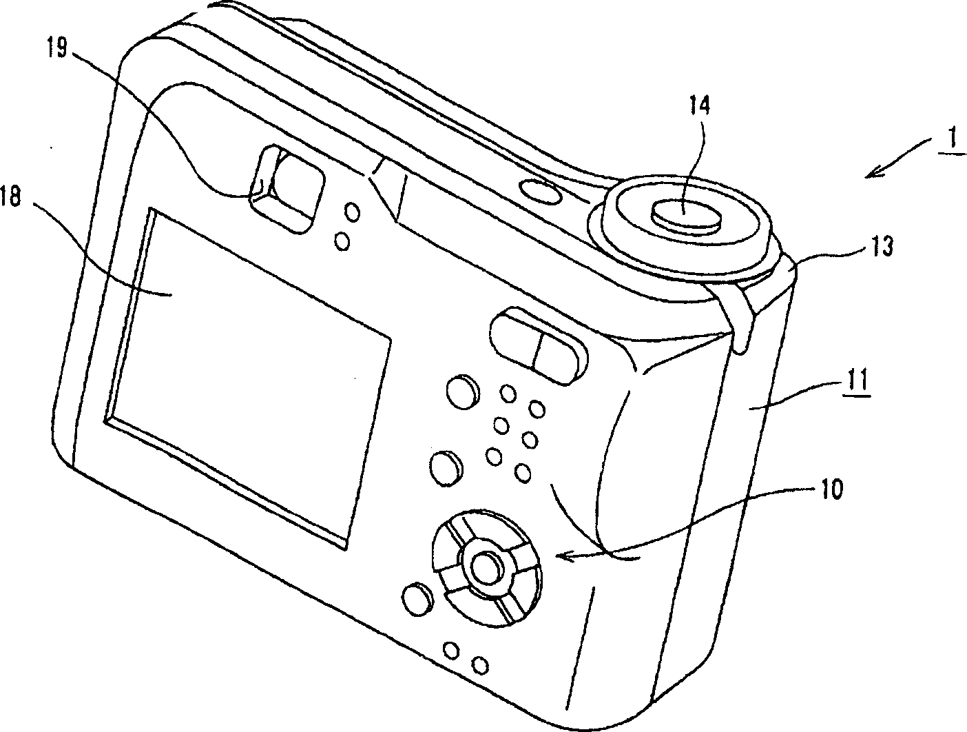
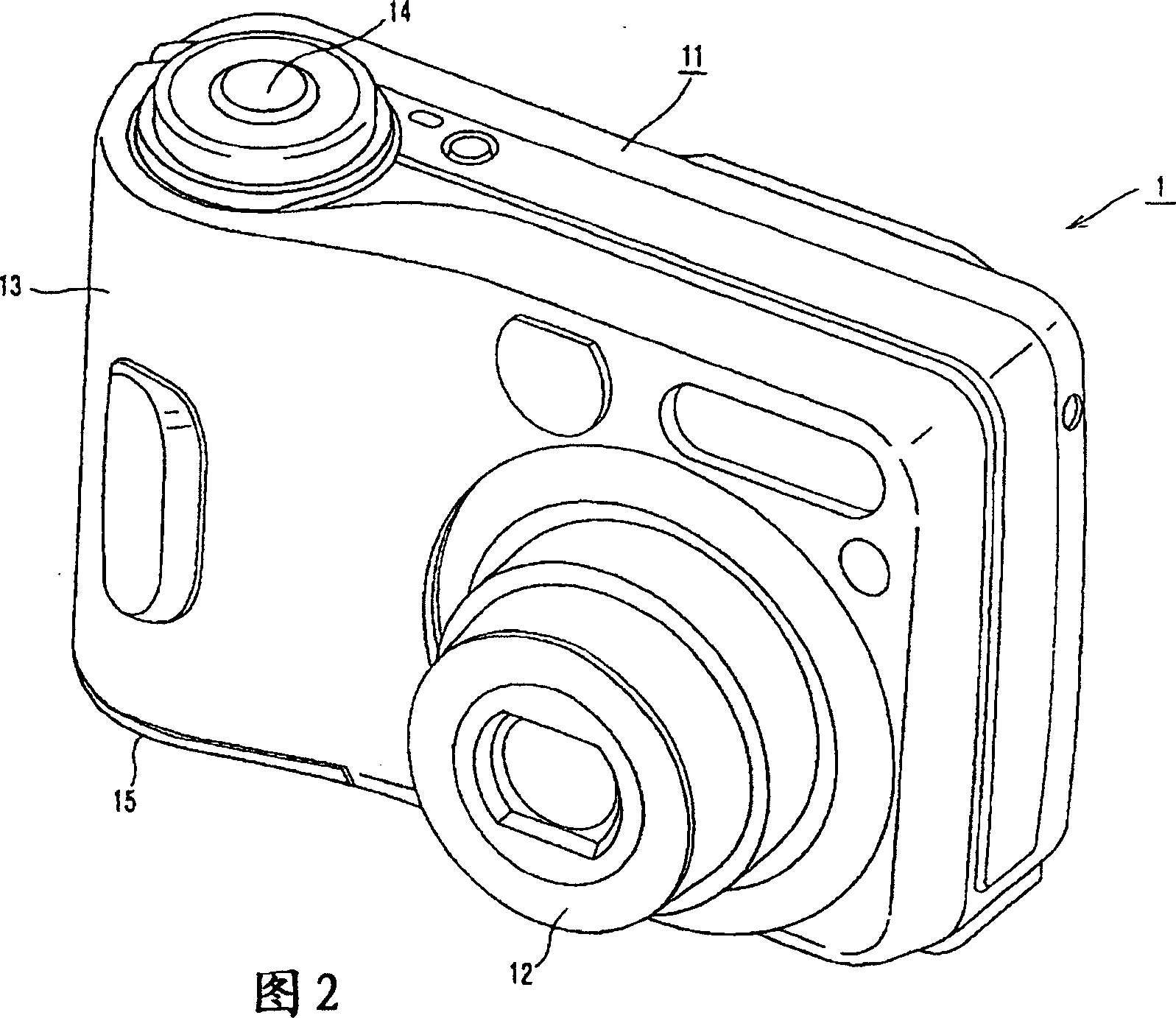
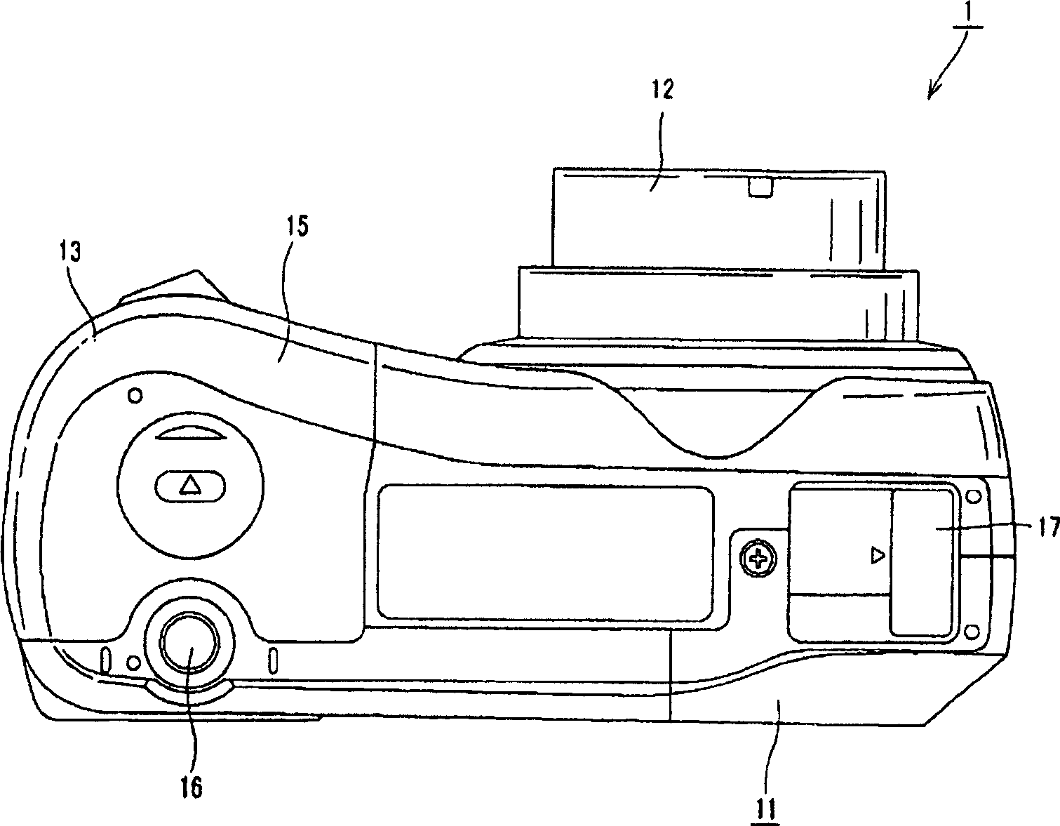
[0036] A digital still camera 1 using the present invention such as Figure 1 ~ Figure 3 As shown, it has a camera main body 11 . The camera main body 11 is provided with a lens unit 12 on one side of the front portion, the lens unit 12 having a lens barrel for accommodating a plurality of lenses, and a grip unit 13 to be gripped by a user on the other side. The handle 13 is shown in Figure 2 and image 3 As shown, the camera unit main body 11 is formed in a shape such that the front side is raised so that it can be held stably by fingers. In addition, a shutter button 14 is provided on the upper face side of the grip portion 13 of the camera body portion 11 .

[0037] A battery housing portion 20 is formed inside the holding portion 13, and the battery housing po...


PUM


Abstract

A DC adaptor which can be installed, alternatively to a primary battery or a secondary battery, on a battery receiving section provided in an electronic apparatus. A DC adaptor (3) is connected to an AC / DC converter (35), installed on a battery receiving section (20) of an electric apparatus (1), and supplies DC power to the electric apparatus. In the DC adaptor, an insertion restriction section (41) is formed on an adaptor body (31) with a substantially circular tube shape. When inserted with correct polarities, the insertion restriction section (41) is guided by an insertion guide section (57) in the battery receiving section, and, when inserted with reversed polarities, the insertion restriction section (41) is restricted, by a side wall (58) on the insertion end side of the battery receiving section, from being inserted into the battery receiving section. The insertion restriction section is projected and formed in a rectangular shape on a part of the outer periphery of the adaptor body, the rectangular shape being in the longitudinal direction of the adaptor body. Two sides (41a, 41b) extended from a part of the outer periphery of the DC adaptor and forming the insertion restriction section are formed such that the center angle of a circular arc connecting their base end sections on the adaptor body is less than 90 DEG .

Description

technical field [0001] The invention relates to a direct current adapter and electronic equipment using the direct current adapter. The direct current adapter is used for externally supplying direct current power to electronic equipment using dry batteries as the power supply. [0002] This application claims priority based on Japanese Patent Application No. 2004-148501 filed on May 19, 2004 and Japanese Patent Application No. 2004-378329 filed on December 27, 2004 in Japan, and these applications are hereby incorporated by reference Apply for citations. Background technique [0003] In the past, electronic devices powered by primary batteries or secondary batteries have been widely used. This type of electronic equipment is provided with a battery housing portion for storing a primary battery or a secondary battery, and is driven by receiving power supply from the battery housed in the battery housing portion. The secondary battery used for this electronic device can be r...

Claims


Application Information

Patent Timeline
IPC IPC(8): H02M3/00H01M2/10H01M50/244H01M50/247
CPCY02E60/10
Inventor 野口敬之庵原真澄奥村由利宫岛洋一阿部英明
Owner SONY CORP
Learn More