
Power outlet for cordless electric appliance

A technology for cordless electrical appliances and power sockets, applied in circuits, electrical components, parts of connecting devices, etc., can solve the problems of wasting electricity, difficult to use, electric shock, etc. Effect

Inactive Publication Date: 2006-07-26
柯赐龙
View PDF1 Cites 1 Cited by
  • Summary
  • Abstract
  • Description
  • Claims
  • Application Information

AI Technical Summary

Problems solved by technology

[0004] However, no matter whether the socket body is arranged on the periphery of the power base or the situation in the center of the power base, their socket bodies are always in a power supply state, so there is a risk of electric shock.
In addition, the socket body is always in the power supply state, and there are repeated heating problems and potential safety hazards of dry burning
Take the electric coffee pot as an example. When people use the electric coffee pot, they are generally used to put the electric coffee pot back on the power base after pouring the coffee, so that the electric coffee pot will work again, causing unnecessary repeated heating. , which wastes electricity and is not conducive to human health. In serious cases, it may even cause dry burning and damage the electric coffee pot.
Although, some power bases are equipped with a manual switch on the side of the power base to control the power on and off for the sake of electrical safety, but in actual use, people often forget to turn off the manual switch after use, so that the Manual switch doesn't work as it should
In addition, for the case where the socket body is set in the center of the power base, because the contact piece located in its central hole or annular groove is always in a live state, therefore, in order to prevent electric shock accidents and ensure the plugging effect, the center The diameter of the hole and the width of the annular groove must be very small, generally not more than 3mm, which makes the user have to carefully align the plug body and the socket body when using, thus affecting the user's convenience; on the other hand, This also limits the size of the power supply base, which is difficult to use when the power of the appliance is larger and requires a larger connector

Method used


Image

  • Power outlet for cordless electric appliance
  • Power outlet for cordless electric appliance
  • Power outlet for cordless electric appliance

Examples


Embodiment 1

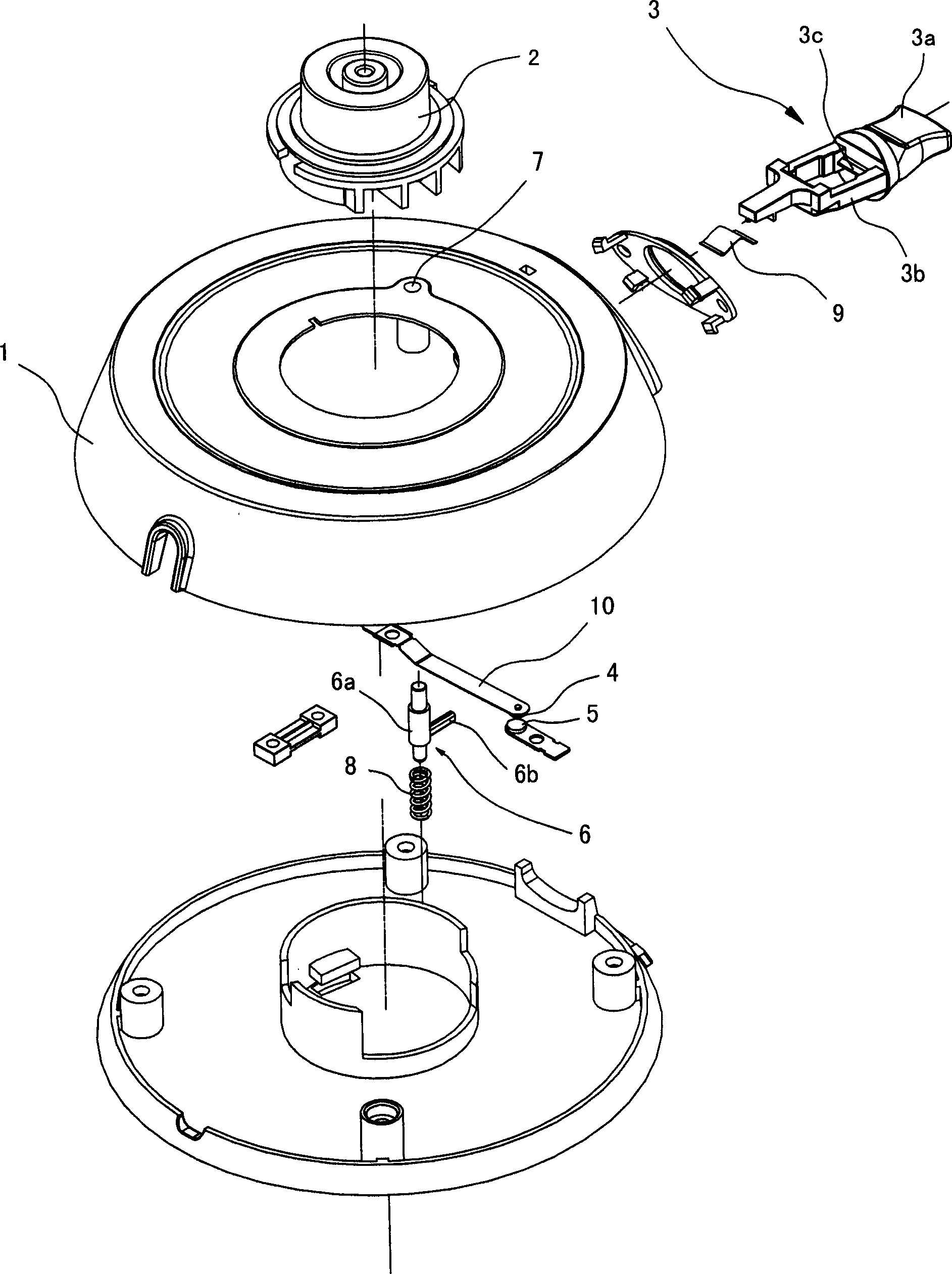
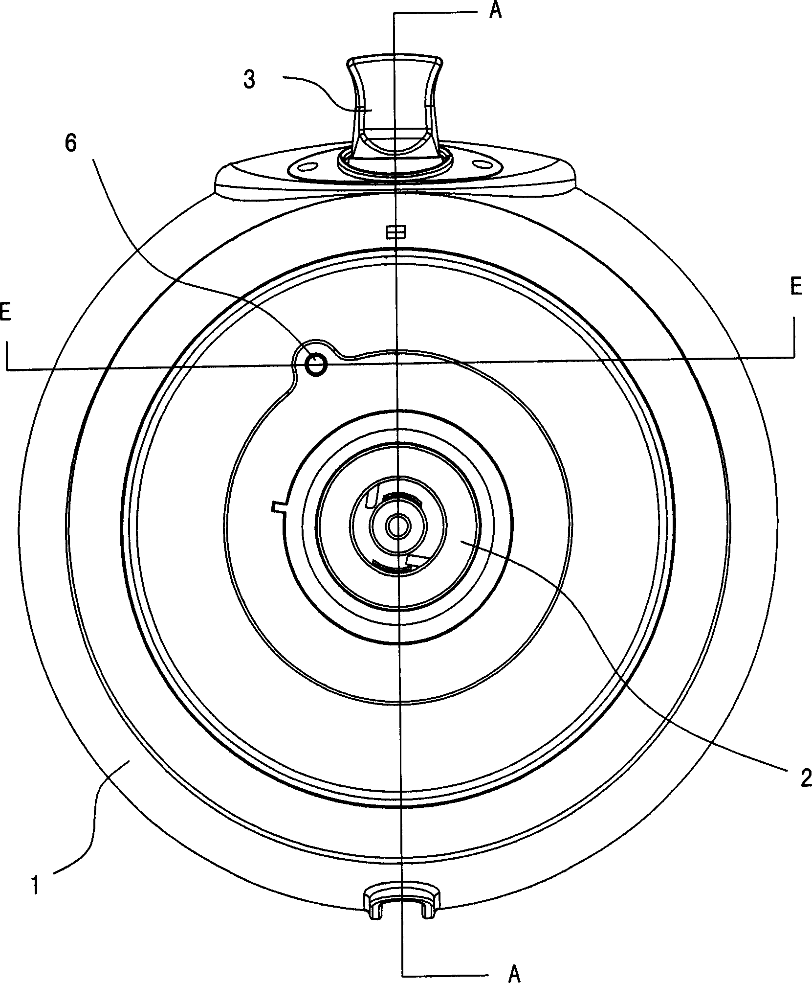
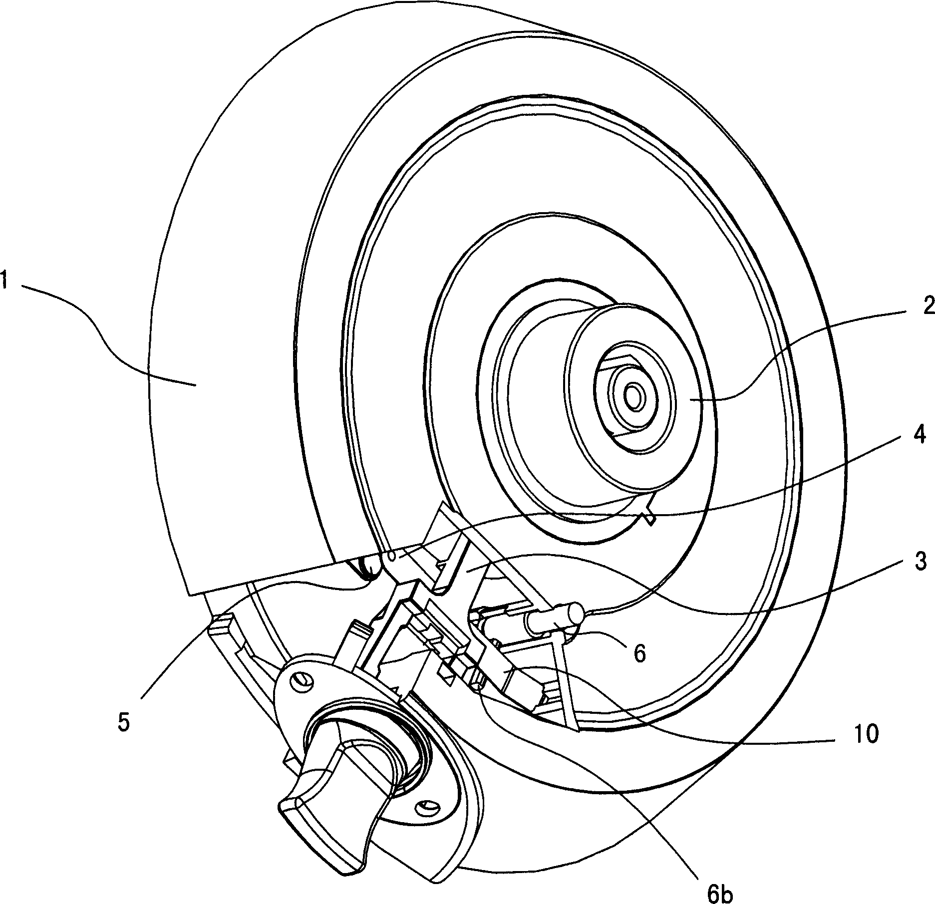
[0030] like Figure 1 to Figure 8 As shown, this embodiment is used for the power base of cordless electrical appliances, which has a base body 1, on which a socket body 2 and a manual switch 3 are arranged, and a pair of moving contacts that cooperate with each other are arranged on the live line in the base body 1 4 and the static contact 5 and the corresponding contact opening and closing control mechanism, the contact opening and closing control mechanism includes a control rod 6 and the manual switch 3, the control rod 6 is in the shape of thin middle and thick at both ends, and the seat body 1 The upper end surface is provided with a through hole 7 that can accommodate the upper end of the control rod 6, and the contact opening and closing control mechanism also includes an elastic mechanism that is arranged in the seat body 1 so that the control rod 6 always has a tendency to extend upwards.

[0031] The elastic mechanism includes a coil spring 8, the upper part of the ...

Embodiment 2

[0035] like Figure 9 As shown, and with reference to the drawings in the first embodiment, this embodiment is used for a power base of a cordless electrical appliance. Compared with the first embodiment, the only difference is that the contact opening and closing control mechanism is different.

[0036] The contact opening and closing control mechanism in this embodiment includes a control rod 6 and the manual switch 3. The control rod 6 has a thin shape at both ends and a thick middle. The protruding through hole 7, the contact opening and closing control mechanism also includes an elastic mechanism arranged in the seat body 1 to make the control rod 6 always have a tendency to protrude upward. The movable contact 4 is arranged on the free end of an elastic sheet 10, and the elastic sheet 10 makes the movable contact 4 have a tendency to move upward all the time; the control rod 6 of the contact opening and closing control mechanism is fixed A horizontally arranged shift le...

Embodiment 3

[0038] like Figure 10 As shown, and with reference to the drawings in the first embodiment, this embodiment is used for a power base of a cordless electrical appliance. Compared with the first embodiment, the only difference is that the contact opening and closing control mechanism is different.

[0039] The contact opening and closing control mechanism in this embodiment includes a control rod 6 and the manual switch 3. The control rod 6 has a thin shape at both ends and a thick middle. The protruding through hole 7, the contact opening and closing control mechanism also includes an elastic mechanism arranged in the seat body 1 to make the control rod 6 always have a tendency to protrude upward. The movable contact 4 is arranged on the free end of an elastic sheet 10, and the elastic sheet 10 makes the movable contact 4 always have a tendency to move downward; Fixedly connected with a horizontally arranged driving rod 6b; the front end of the manual switch 3 and the driving...


PUM


Abstract

This invention discloses one wireless appliance socket, which has socket base with plug socket and handle switch and is characterized by the following: the socket fire circuit sets one pair of matching dynamic and stoic probes and relative probe switch control device which comprises elastic structure stretching upwards to make the control bar and to make it separate with dynamic and static probes.

Description

technical field [0001] The invention relates to an electric connector, in particular to a power base for separate cordless electric appliances such as a cordless electric kettle, a cordless electric coffee pot, a cordless frying pan, and a cordless electric iron. Background technique [0002] In existing cordless electric kettles, cordless electric coffee pots, cordless frying pans, cordless electric irons and other separate cordless electrical appliances, a plug body is generally arranged at the bottom of the electrical appliance body, and a matching power supply base ( That is, the power base) is provided with a socket body. When the electrical appliance body is placed on the base, the plug body and the socket body are inserted into each other, thereby realizing the power supply to the electrical appliance body. A common situation is: the plug body has a straight column terminal. Due to the limitation of its structure, the plug body and the socket body are respectively loc...

Claims


Application Information

Patent Timeline
Patent Type & Authority Applications(China)
IPC IPC(8): H01R13/70H01H3/46
Inventor 柯赐龙
Owner 柯赐龙
Learn More