Detachable antenna device for portable terminal

A technology for a portable terminal and an antenna device, which is applied in the directions of quickly disassembling an antenna unit, an antenna support/installation device, an antenna, etc., can solve the problems of reducing the portability and compactness of the terminal, etc.

Inactive Publication Date: 2006-08-02
SAMSUNG ELECTRONICS CO LTD
View PDF0 Cites 3 Cited by
  • Summary
  • Abstract
  • Description
  • Claims
  • Application Information

AI Technical Summary

Problems solved by technology

Therefore, for this service, the antenna device permanently installed on the portable terminal reduces the portability and compactness of the terminal.

Method used


Image

  • Detachable antenna device for portable terminal
  • Detachable antenna device for portable terminal
  • Detachable antenna device for portable terminal

Examples


Embodiment Construction

[0022] Hereinafter, preferred embodiments of the present invention will be described with reference to the drawings. In the following description of the present invention, detailed descriptions of known functions and structures incorporated herein are omitted to avoid making the subject matter of the present invention unclear.

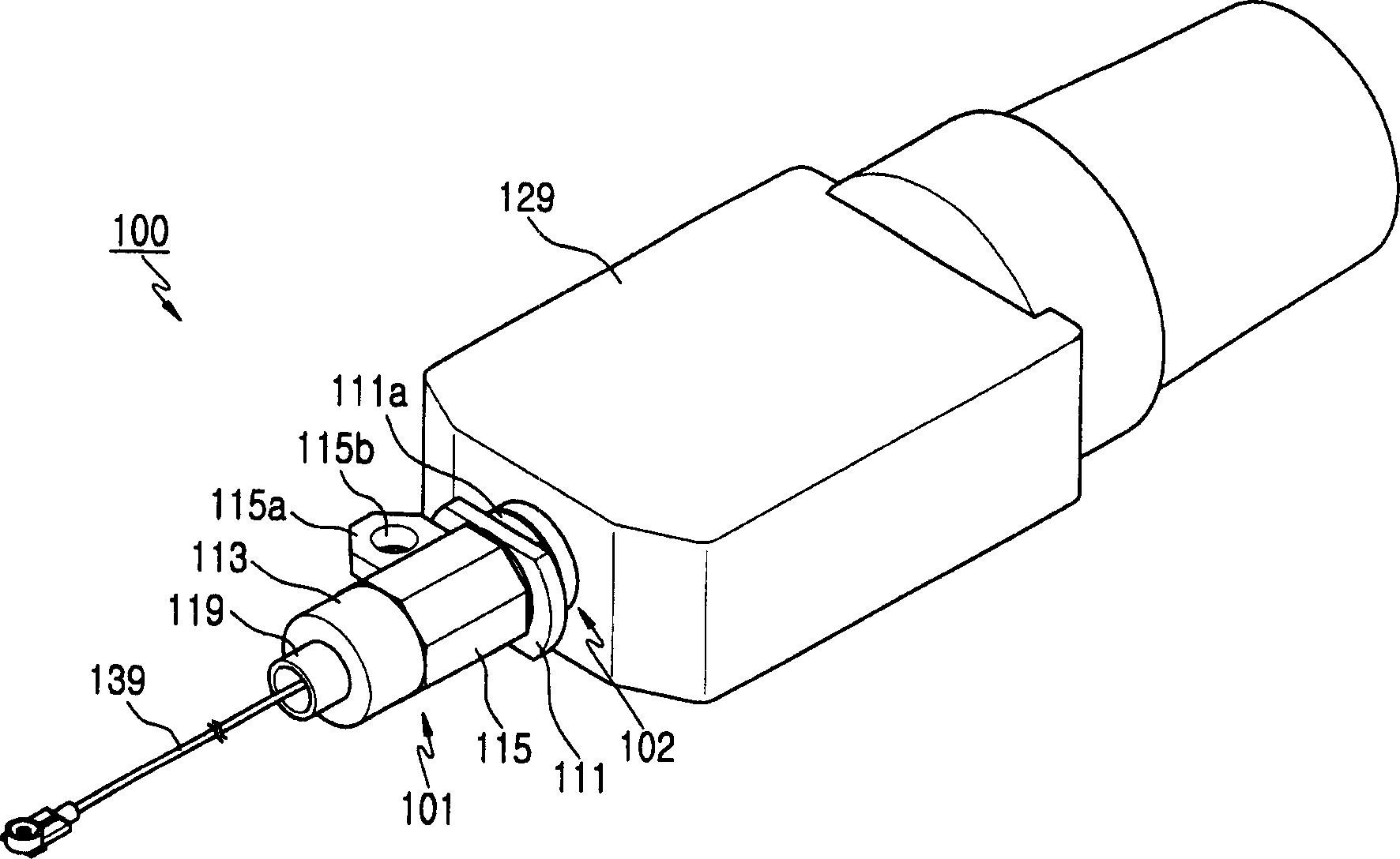
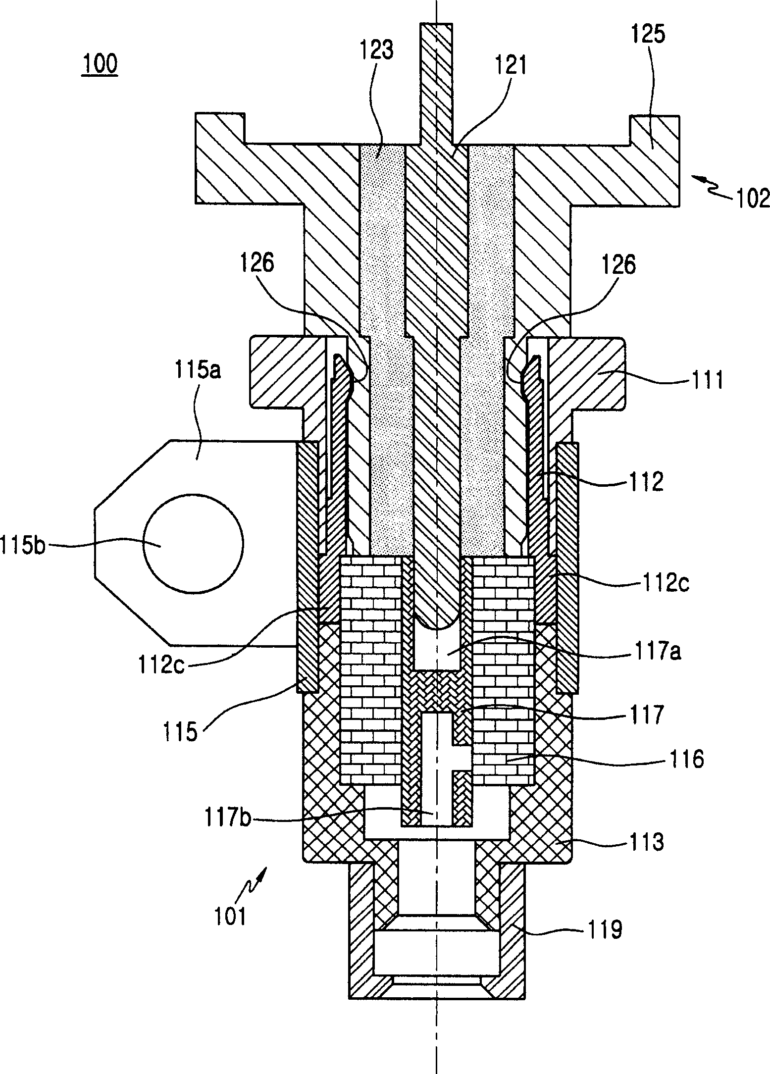
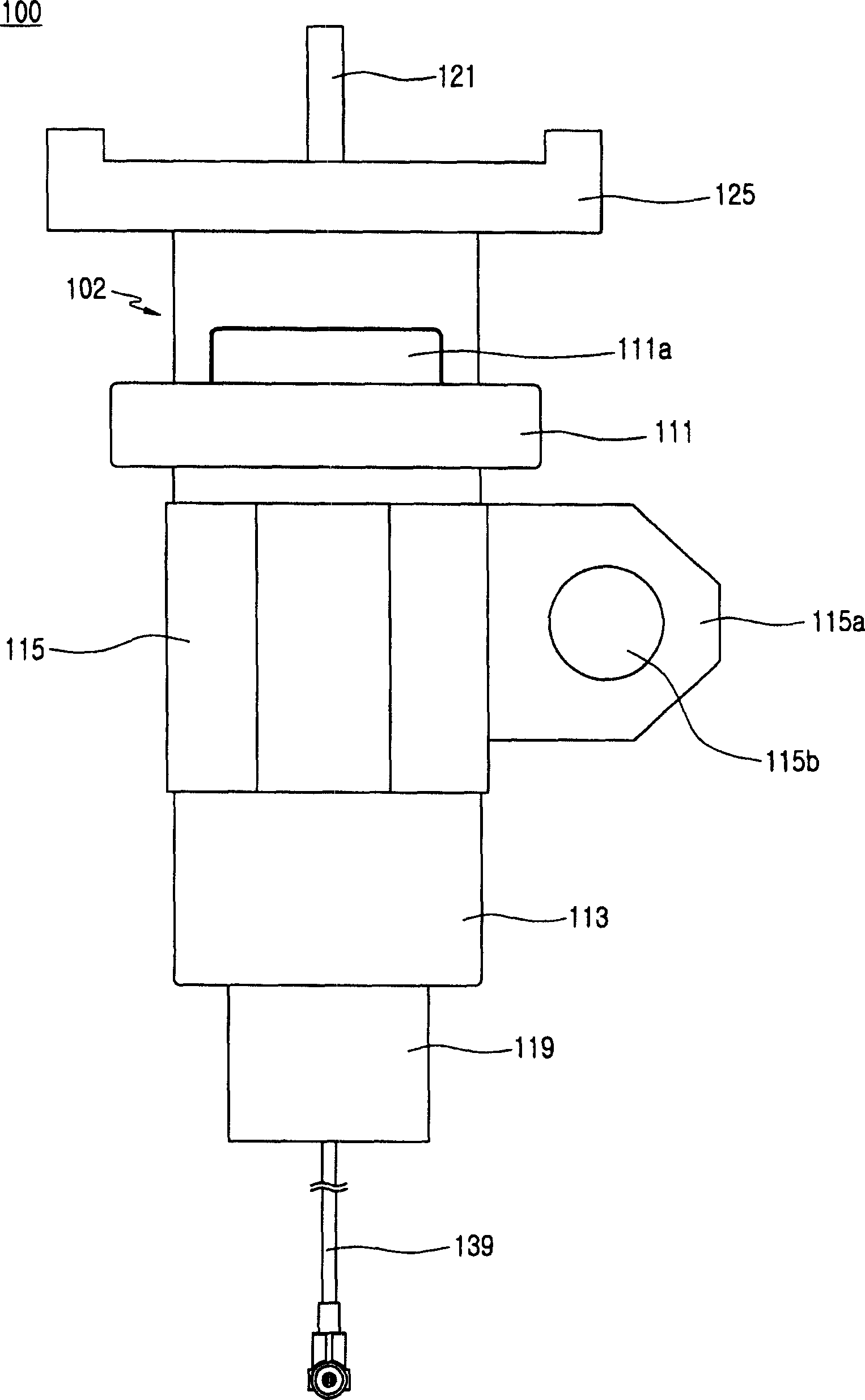
[0023] figure 1 is a perspective view of a detachable antenna device for a portable terminal according to a preferred embodiment of the present invention, Figure 2 to Figure 4 are shown respectively figure 1 The connector 100 of the antenna device.

[0024] like Figure 1 to Figure 4 As shown, the antenna device has a connector 100 including a socket 101 mounted on a terminal and a plug 102 mounted on an antenna emitting unit 129 to be connected to the socket 101 . The connector 100 of the antenna device makes the transmitting unit 129 combine on the terminal 10 and from the terminal 10 (such as Figure 5 shown) disassembled. The connector 100 h...


PUM


Abstract

Disclosed herein is detachable antenna device for a portable terminal that includes a socket installed on any one of the terminal and a radiation unit of the antenna device, a plug installed on the other one of the terminal and the radiation unit of the antenna device and adapted to be coupled to the socket, and a position retaining means for limiting the rotation of the radiation unit when the plug is coupled to the socket. The detachable antenna device for a portable terminal can be mounted on a terminal as desired, and particularly, it can be used for TV watching and performing GPS information terminal functions. It can also be detached from the terminal in a normal state for improved compactness and portability of the terminal. The connector of the antenna device is prevented from being worn and damaged by an external factor to improve the durability and retain the plug in a more stable manner.

Description

technical field [0001] The present invention relates to portable terminals, and more particularly, to a detachable antenna device for a portable terminal. Background technique [0002] Generally, a portable terminal provides electrical communication between users or between a user and a service provider, and conducts various services including voice communication, short message service, multimedia service, and entertainment service. [0003] According to their appearance, portable terminals can be classified into: bar type terminals, which have a transmitting unit, receiving unit, and data input / output device on a single housing; flip type terminals, which, as in the case of bar type terminals, have The transmitting unit, the receiving unit and the data input / output device also have a flip cover combined with a single housing, which can expose or hide the data input device, such as a keypad; a folding terminal, which has a pair of foldable The tran...

Claims


Application Information

Patent Timeline
Patent Type & Authority Applications(China)
IPC IPC(8): H01Q1/24
CPCH01Q1/088H01Q1/242H04B1/38H01Q1/24
Inventor 车桄焕
Owner SAMSUNG ELECTRONICS CO LTD
Why Eureka
Try Eureka