
Multi-area vertical calibrating liquid crystal display device

A liquid crystal display device, multi-area technology, used in static indicators, nonlinear optics, instruments, etc., can solve the problems of reduced display quality and uneven panel brightness.

Active Publication Date: 2006-08-09
AU OPTRONICS CORP
View PDF0 Cites 12 Cited by
  • Summary
  • Abstract
  • Description
  • Claims
  • Application Information

AI Technical Summary

Problems solved by technology

When this effect spreads to the entire panel display area, it will cause uneven brightness of the panel and lower display quality, so it is urgent to improve

Method used


Image

  • Multi-area vertical calibrating liquid crystal display device
  • Multi-area vertical calibrating liquid crystal display device
  • Multi-area vertical calibrating liquid crystal display device

Examples


Embodiment Construction

[0025] First, please refer to FIG. 2(a) and FIG. 2(b), which are side views and top views of the multi-region calibration display device of the present invention, the multi-region calibration display device includes a first substrate 1, a second substrate 2 and a negative Type liquid crystal layer 7. 2( a ) and FIG. 2( b ) show a first electrode 11 , a plurality of protrusions 3 , a pixel electrode 4 , a first slit 5 and a second slit 6 . Wherein the first electrode 11 is located on the surface of the first substrate 1 , and the surface of the first substrate 1 has a plurality of protrusions 3 . The pixel electrodes 4 on the surface of the second substrate 2 have a plurality of first slits 5 parallel to the protrusions 3 for separating the pixel electrodes 4 . The second slit 6 is positioned at the edge of the first slit 5, and its extension direction and the projection 3 are perpendicular to the projection of the second substrate 2, and the length (L) of the second slit 6 st...


PUM


Abstract

The liquid crystal display unit consists of following parts: first base plate including multiple bulges and first electrode; second base plate of possessing multiple pixel electrodes, first slits, and second slits; a liquid crystal layer located between the first base plate and the second base plate. The first electrode is positioned on surface of the first base plate, and bulges are positioned on part of surface of the first electrode. Pixel electrodes are on surface of the second base plate. First slits are located between pixel electrodes. First slits and bulges are not interleaved with projection of second base plate. Second slit is located at edge of first slit. Extended directions of second slits and bulges are interleaved with projection of second base plate.

Description

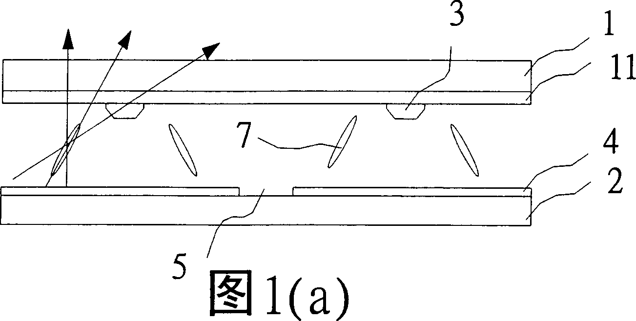
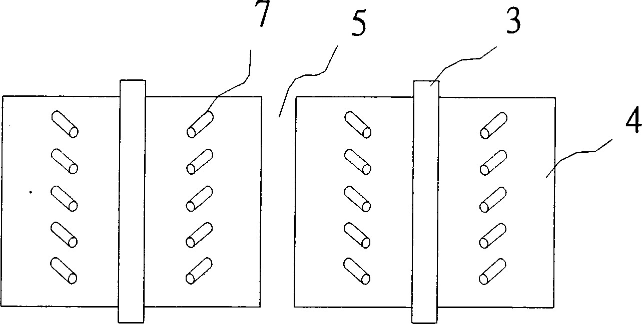
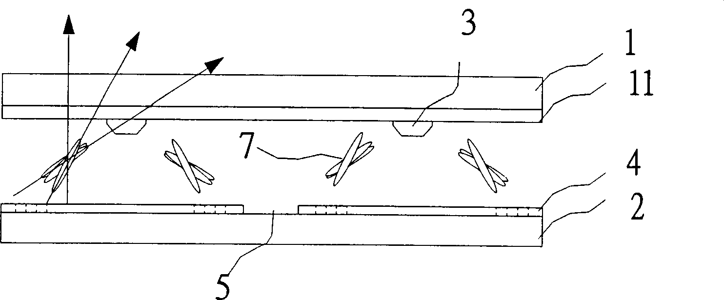
【Technical field】 [0001] The invention relates to a liquid crystal display device, in particular to a liquid crystal display device suitable for multi-region vertical calibration. 【Background technique】 [0002] At present, the development goal of liquid crystal display is to develop towards large size, high brightness, high contrast, wide viewing angle, and high color saturation. A solution to the problem. In the MVA liquid crystal display device, since the display area is divided into multiple areas, the liquid crystals are arranged in a mutually compensating manner, so the same phase difference value can be seen at different viewing angles without gray scale inversion. phenomenon, while also improving contrast and shortening response time. [0003] The side view and the top view of the known MVA liquid crystal display device are shown in Fig. Protrusion 3 (protrusion): The pixel electrodes 4 are located on the surface of the second substrate 2, and there are a pluralit...

Claims


Application Information

Patent Timeline
IPC IPC(8): G02F1/1343G02F1/133G02F1/136
Inventor 李锡烈
Owner AU OPTRONICS CORP
Learn More