Multi-display device and image display device

a multi-display and image display technology, applied in the field of multi-display devices, can solve the problems of uneven luminance, inconvenience to observers, and inconvenient viewing, and achieve the effects of low power consumption, high-quality image display, and low luminance distribution

Active Publication Date: 2016-01-19
ELUX INC
View PDF9 Cites 1 Cited by
  • Summary
  • Abstract
  • Description
  • Claims
  • Application Information

AI Technical Summary

Benefits of technology

[0025]According to the present invention, by controlling the image-display-light emitting means of each of the plurality of image display devices to emit planar light with optimal luminance distribution in accordance with the arrangement, direction, and number thereof, it is possible to provide a multi-display device capable of providing high-quality image display with low power consumption without degradation of display quality. Further, it is possible to provide an image display device that constitutes such a multi-display device.

Problems solved by technology

A typical multi-display device employs liquid crystal displays having the same luminance of images, but in practice, the luminance of images for the liquid crystal displays may vary due to individual differences which cause luminance unevenness.
In such a multi-display device, if variance occurs in the luminance of images displayed on the respective liquid crystal displays, continuity between the images is deteriorated, which may cause inconvenience to an observer.

Method used


Image

  • Multi-display device and image display device
  • Multi-display device and image display device
  • Multi-display device and image display device

Examples


first embodiment

Configuration of Multi-Display Device

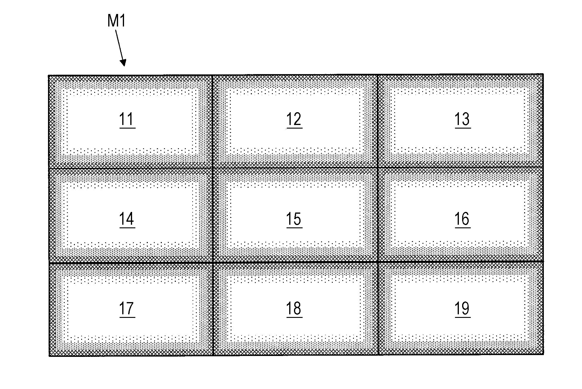
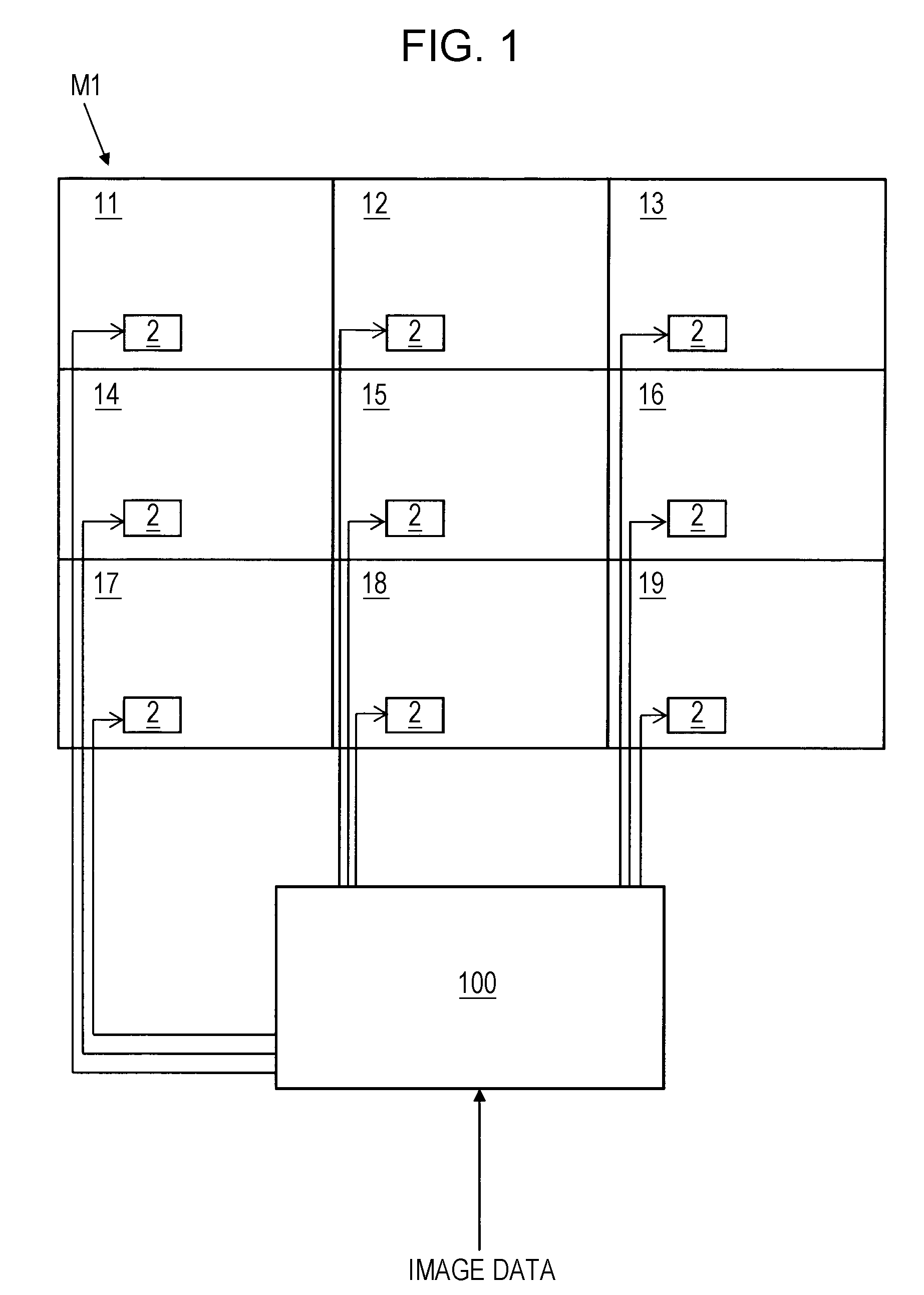
[0055]FIG. 1 is a diagram illustrating an overall configuration of an example of a multi-display device according to an embodiment of the present invention. As shown in FIG. 1, a multi-display device M1 includes nine liquid crystal displays 11 to 19 and an image distributer 100. As shown in FIG. 1, in the multi-display device M1, nine liquid crystal displays are arranged in horizontal orientation in the form of 3 (width)×3 (height).

[0056]The image distributer 100 is connected to each of the nine liquid crystal displays 11 to 19. The image distributor 100 divides image data on an image corresponding to one screen transmitted from an optical disc device such as a DVD device or a BD device, a personal computer, or the like into data on nine images to be displayed in the nine liquid crystal displays 11 to 19, and outputs image data corresponding to each screen to the liquid crystal displays 11 to 19. Further, the image distributor 100 may also transm...

second embodiment

[0124]In the above-described multi-display device, when the PWM values are not corrected, a liquid crystal display capable of emitting planar light with uniform luminance distribution is used. On the other hand, there is a liquid crystal display (image display device with uniform luminance distribution) that includes a backlight unit that emits planar light with luminance distribution in consideration of sensitivity features of human vision, without correction using the arrangement of the LEDs 62, reflection at the peripheral part, and the like.

[0125]In a case where a multi-display device includes a liquid crystal display with non-uniform luminance distribution, by providing tables corresponding to a liquid crystal display that uses a backlight unit with non-uniform luminance distribution in a multi-luminance correction filter group, it is possible to optimize luminance distribution of the multi-display device.

[0126]On the other hand, in a multi-display device that includes both of ...

third embodiment

[0129]A correction method of PWM values in a luminance correcting section provided in a liquid crystal display according to an embodiment of the present invention will be described with reference to the accompanying drawings. FIG. 12 is a block diagram illustrating another example of a liquid crystal display, and FIG. 13 is a diagram illustrating correction of PWM values in the luminance correcting section. As shown in FIG. 12, a liquid crystal display 1B has the same configuration as that of the liquid crystal display 1 shown in FIG. 3 except for a luminance correcting section 58, in which the same reference numerals are given to substantially the same sections, and description about the same sections will be omitted. As shown in FIG. 11, the luminance correcting section 58 includes an X correcting part 581 and a Y correcting part 582. Luminance correction shown in FIG. 13 is an example, in which the PWM value set to each of the areas 600 is 4095.

[0130]The X correcting part 581 cor...


PUM


Abstract

A multi-display device includes an image-display-light emitting backlight which includes a light emitting element arranged in each of a plurality of areas to emit light to form planar light; and a light emission controller configured or programmed to generate emission luminance data, for each of the areas, to drive the light emitting element. The light emission controller includes a luminance correcting controller configured or programmed to correct the emission luminance data on the basis of installation directions of image display devices and connection information that is information on connection positions thereof.

Description

TECHNICAL FIELD[0001]The present invention relates to a multi-display device in which a plurality of image display devices are arranged, and an image display device that constitutes the multi-display device.BACKGROUND ART[0002]In recent years, in a place where a lot of people gather, such as an event site, a station, or an airport, a multi-display device in which a plurality of liquid crystal displays are arranged vertically or horizontally, or vertically and horizontally has been installed to display a large amount of information. In the multi-display device, the liquid crystal displays display images corresponding to their installation places to display a large-screen image.[0003]A typical multi-display device employs liquid crystal displays having the same luminance of images, but in practice, the luminance of images for the liquid crystal displays may vary due to individual differences which cause luminance unevenness. In such a multi-display device, if variance occurs in the lu...

Claims


Application Information

Patent Timeline
Patent Type & Authority Patents(United States)
IPC IPC(8): G09G3/34G06F3/14H04N5/66H04N21/431H04N21/442H04N21/443H04N21/422H04N5/57G09G5/06
CPCG09G3/3406G06F3/1446G09G3/3426H04N5/57H04N5/66H04N21/42202H04N21/4316H04N21/4318H04N21/4436H04N21/44218G09G5/06G09G2300/026G09G2310/0232G09G2320/0233G09G2320/0238G09G2320/064G09G2320/0666G09G2320/08G09G2356/00
Inventor ICHIOKA, HIDEKIMURAI, TAKAYUKIKONDOH, NAOKO
Owner ELUX INC
Why Eureka
Try Eureka