
Posteriorly fitted room mirror for automobile

A technology for interior rearview mirrors and compartments, applied to vehicle parts, transportation and packaging, optical observation devices, etc., can solve the problems of increasing double-sided tapes, increasing manufacturing processes, and peeling of cushioning materials 14, so as to reduce the number of parts, Effects of preventing theft and reducing the manufacturing process

Inactive Publication Date: 2006-08-16
CAR MATE MFG
View PDF0 Cites 0 Cited by
  • Summary
  • Abstract
  • Description
  • Claims
  • Application Information

AI Technical Summary

Problems solved by technology

[0006] However, in the conventional interior rearview mirror for automobiles for rear installation, after the annular portion 11 of the spring 10 is fitted with the protrusion 9 during assembly, in order to prevent the spring 10 from falling out, The fixture 13 must be firmly connected to the raised portion 9, thereby increasing the manufacturing process of this part and increasing the number of parts of the fixture 13
[0007] Also, since the cushioning material 14 is fixed on the lower jaw 4 by using a double-sided tape, the number of parts of the double-sided tape part is increased, and when assembling the interior rearview mirror, the adhesive surface of the protective double-sided tape is peeled off. The cover is very troublesome, and the deterioration of the adhesive part of the double-sided tape caused by heat during the use of the interior rearview mirror of an automobile may sometimes cause the cushioning material 14 to peel off from the lower jaw 4.
[0008] Also, if the fixture 13 is not used but Figure 19 In the shown structure, a flange portion 15 protruding outward in the radial direction is provided on the front end of the outer peripheral surface of the raised portion 9 to prevent the spring 10 fitted with the raised portion 9 from falling off, although parts can also be reduced. number, but when the annular portion 11 of the spring 10 is fitted with the protruding portion 9, it is necessary to provide a process of enlarging the inner diameter of the annular portion 11 of the spring 10, which increases the manufacturing process.

Method used


Image

  • Posteriorly fitted room mirror for automobile
  • Posteriorly fitted room mirror for automobile
  • Posteriorly fitted room mirror for automobile

Examples


Embodiment Construction

[0035] Embodiments of the present invention will be described below with reference to the drawings.

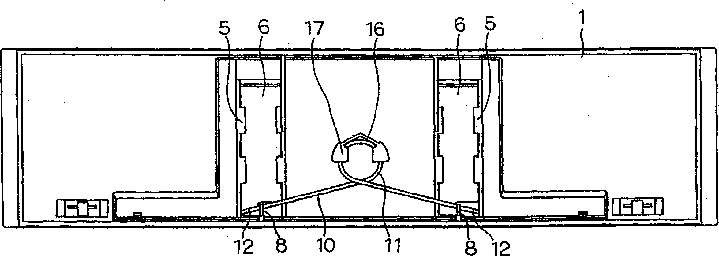
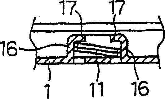
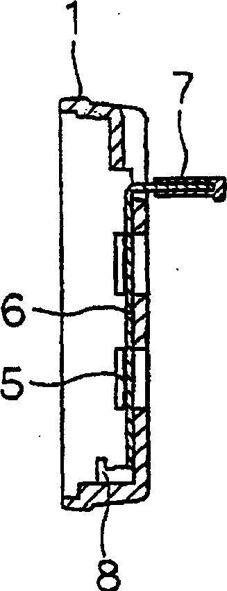
[0036] In the present invention, as Figure 1 ~ Figure 4 As shown, a pair of left and right abutment portions or abutment walls 16, 16 abutting against the outer peripheral surface of the annular portion 11 of the spring 10 are provided, and the front ends of the abutment walls 16 protrude radially inwardly, and The protruding portion 9 is provided at the front central portion of the rearview mirror body 1 of the vehicle interior instead of the flange portion 17 that covers a part of the end surface of the annular portion 11 to prevent the annular portion from falling out.

[0037] The automotive interior rearview mirror for rear installation of the present invention adopts the above-mentioned structure, so when it is assembled, if the end surface of the ring-shaped part 11 of the spring 10 passes through the flange part 17 that prevents the ring-shaped part from coming out T...


PUM


Abstract

The invention relates to a posteriorly fitted rearview mirror for automobile, which comprises a posteriorly fitted rearview mirror body installed in the front of the existing rearview mirror; a reflection mirror arranged in the front of the rearview mirror body; a jaw section arranged on either the top or the bottom part of the back of the rearview mirror body; a freely movable jaw section arranged on the opposite part of the back of the rearview mirror body; a force applying device for ever-applying a force towards the jaw section to the freely movable jaw section; guide walls respectively arranged on both sides of the surface of at least one of the two jaw sections and with grooves in opposite positions; protrusions arranged on the surface of the jaw sections; and an elastic component provided with protrusions engaging with the grooves on both sides thereof and with recess portions engaging with the protrusions on the lower surface. Compared with conventional posteriorly fitted rearview mirrors, the invention has reduced number of parts and manufacturing procedures.

Description

[0001] This application is a divisional application of the invention patent application whose application number is 03104158.2 and which is entitled "Automotive Interior Rearview Mirror for Rear-fitting". technical field [0002] The present invention relates to an automobile interior rearview mirror for rear installation, in particular to an automobile interior rearview mirror for rear installation used to cover the front of the original interior rearview mirror in a vehicle. Background technique [0003] Figure 16 ~ Figure 18 Represents a conventional interior rearview mirror for automobiles for rear installation. 1 is a box-shaped interior rearview mirror body for rear installation that is installed in front of the original interior rearview mirror 2 in the car and has an opening on the front side. 3 4 is a reflector fixed to the edge of the interior rearview mirror body 1 by blocking the opening on the front side of the interior mirror body 1. The lower jaws 5 are groov...

Claims


Application Information

Patent Timeline
IPC IPC(8): B60R1/04
CPCB60R1/04B60R1/082B60R1/12B60R2001/1292
Inventor 佐佐木广
Owner CAR MATE MFG
Learn More