Refrigerator

A technology of refrigerators and coolers, applied in the field of refrigerators, which can solve problems such as longer cooling operation time, lower cooling capacity, and flow, and achieve the effects of improving cooling efficiency, eliminating cooling loss, and eliminating flow noise

Active Publication Date: 2006-08-16
TOSHIBA LIFESTYLE PROD & SERVICES CORP
View PDF1 Cites 6 Cited by
  • Summary
  • Abstract
  • Description
  • Claims
  • Application Information

AI Technical Summary

Problems solved by technology

[0007] However, the suction operation itself in the above-mentioned conventional example is not only not conducive to indoor cooling, but also when the compressor 12 rotates at a high speed when the ambient temperature of the refrigerator is high or when high-temperature food is placed in the refrigerator, if the In this way, when the suction operation is performed at this rotational speed, when the three-way valve 14 is switched to the refrigeration side circuit 21 in order to perform the refrigeration side cooling operation after the suction operation, the refrigerant stored in the condenser 13 by the suction operation will be reduced. A large amount of pressure is sent by the high-speed compressor 12 to the refrigerating cooler 9 in the gap state.
As a result, the sound of the refrigerant flowing suddenly becomes louder and becomes a noise, and there is a problem that the user may feel uncomfortable due to the intermittent abnormal sound of the refrigerant flowing.
[0008] In addition, according to Patent Document 1, although it is possible to prevent the delay of the refrigerant in the refrigerating cooler when switching from the cooling operation of the refrigerating side circuit to the operation of the refrigerating side circuit, since the refrigerant flows in both the refrigerating and refrigerating side circuits, the The cooling capacity is reduced, and for some load conditions in the refrigerating room, there are disadvantages such as longer time for simultaneous cooling operation and poor efficiency
In addition, the flow resistance of the refrigerant flow path toward the refrigerator for refrigeration is set to be smaller than that of the refrigerant flow path toward the cooler for freezing, so that in the refrigeration cooling mode in which the refrigerant flows only in the cooler for refrigeration , operates at a high evaporating temperature, so when the refrigerant flows toward both sides, there is a problem that more refrigerant flows toward the side of the cooler for refrigeration

Method used


Image

  • Refrigerator
  • Refrigerator
  • Refrigerator

Examples


Embodiment Construction

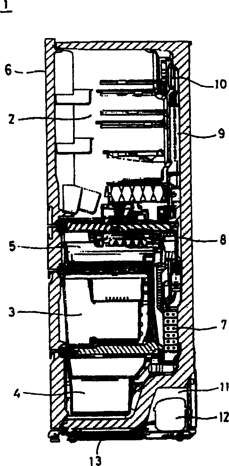
[0021] An embodiment of the present invention will be described below with reference to the accompanying drawings. figure 2 It is a vertical cross-sectional view of the refrigerator. The interior of the refrigerator main body 1 formed by the heat-insulating box is used as a storage space, and the refrigerator compartment 2 is independently arranged on the uppermost part, the vegetable compartment 3 is arranged below the refrigerator compartment 2, and the freezer compartment is arranged on the lowermost part. 4. Between the refrigerator compartment 2 and the vegetable compartment 3, an automatic ice-making compartment 5 and an unillustrated multi-temperature switching compartment are arranged side by side through a heat-insulating partition wall. The front openings of each storage compartment are respectively provided with dedicated doors. 6. Seal it freely with opening and closing.

[0022] A cooler 7 for refrigerated storage spaces such as a freezer and an ice-making room, ...


PUM


Abstract

A refrigerator, coolers (7, 9) for exclusively cooling freezing and refrigerating spaces respectively, and cool air circulating fans (8, 10) are provided, cooling is performed by alternately switching the refrigerant passage to the coolers for freezing and refrigeration by a passage switching valve (14). and when switching the refrigerant passage from the cooler (7) for freezing to the cooler (9) for refrigeration, the refrigerator is operated in a refrigeration cooling mode after operating both coolers in a simultaneous cooling mode. When operating the refrigerator in the simultaneous cooling mode, if a temperature difference between the refrigerant entrance and exit parts of the cooler for refrigeration is not more than a prescribed value, passage resistance to the cooler for refrigeration is made large, and if it is not less than the prescribed value, the passage resistance is made small. Abnormal noise is prevented from generating, by performing highly efficient cooling operation by reducing a cooling loss due to refrigerant delay caused when switching a passage, when switching operation from cooling operation of a freezing side circuit to a refrigeration side circuit by a refrigerant passage switching device such as a three way valve, and by supplying well-balanced flow of the refrigerant to respective coolers for freezing and refrigeration.

Description

technical field [0001] The invention relates to a refrigerator, which is provided with a cooler for cooling a freezing storage space and a refrigerating storage space, and a fan for circulating cold air, and alternately cools the freezing and refrigerating storage spaces through a flow path switching valve. Background technique [0002] Figure 8 It shows the refrigerating cycle of a conventional refrigerator. As the compressor 12 that compresses and discharges the refrigerant, a variable capacity compressor is used. A condenser 13, a refrigerant flow switching device composed of a three-way valve 14, and 1. The throttling device 15 and the cooler 9 for refrigeration are connected to the compressor 12, and the second throttling device 16 and the cooler 7 for freezing, the accumulator 17 and the one-way valve 18 are connected to the first throttling device 15 and The coolers 9 for refrigeration are connected in parallel to form a refrigeration cycle 20 . [0003] And, accord...

Claims


Application Information

Patent Timeline
Patent Type & Authority Applications(China)
IPC IPC(8): F25D11/02
CPCF25B2600/2511F25D29/00F25D19/006F25B49/022F25D11/022F25B2600/0253F25D2700/10F25B2700/21174F25B2700/21175F25B41/20F25B2500/12
Inventor 野口好文天明稔仁木茂塚本惠造
Owner TOSHIBA LIFESTYLE PROD & SERVICES CORP
Why Eureka
Try Eureka