Applying apparatus

A technology of coating device and moving device, which is applied in the direction of surface coating liquid device, spraying device, coating, etc., which can solve the deformation of the door-shaped moving mechanism, the inability to move the left and right moving bodies completely synchronously, and the slit nozzle Deformation and other problems, to achieve the effect of the center of gravity

Active Publication Date: 2006-08-30
艾美柯技术株式会社
View PDF2 Cites 17 Cited by
  • Summary
  • Abstract
  • Description
  • Claims
  • Application Information

AI Technical Summary

Problems solved by technology

However, even with this configuration, it is impossible to move the left and right moving bodies completely synch

Method used


Image

  • Applying apparatus
  • Applying apparatus
  • Applying apparatus

Examples


Embodiment Construction

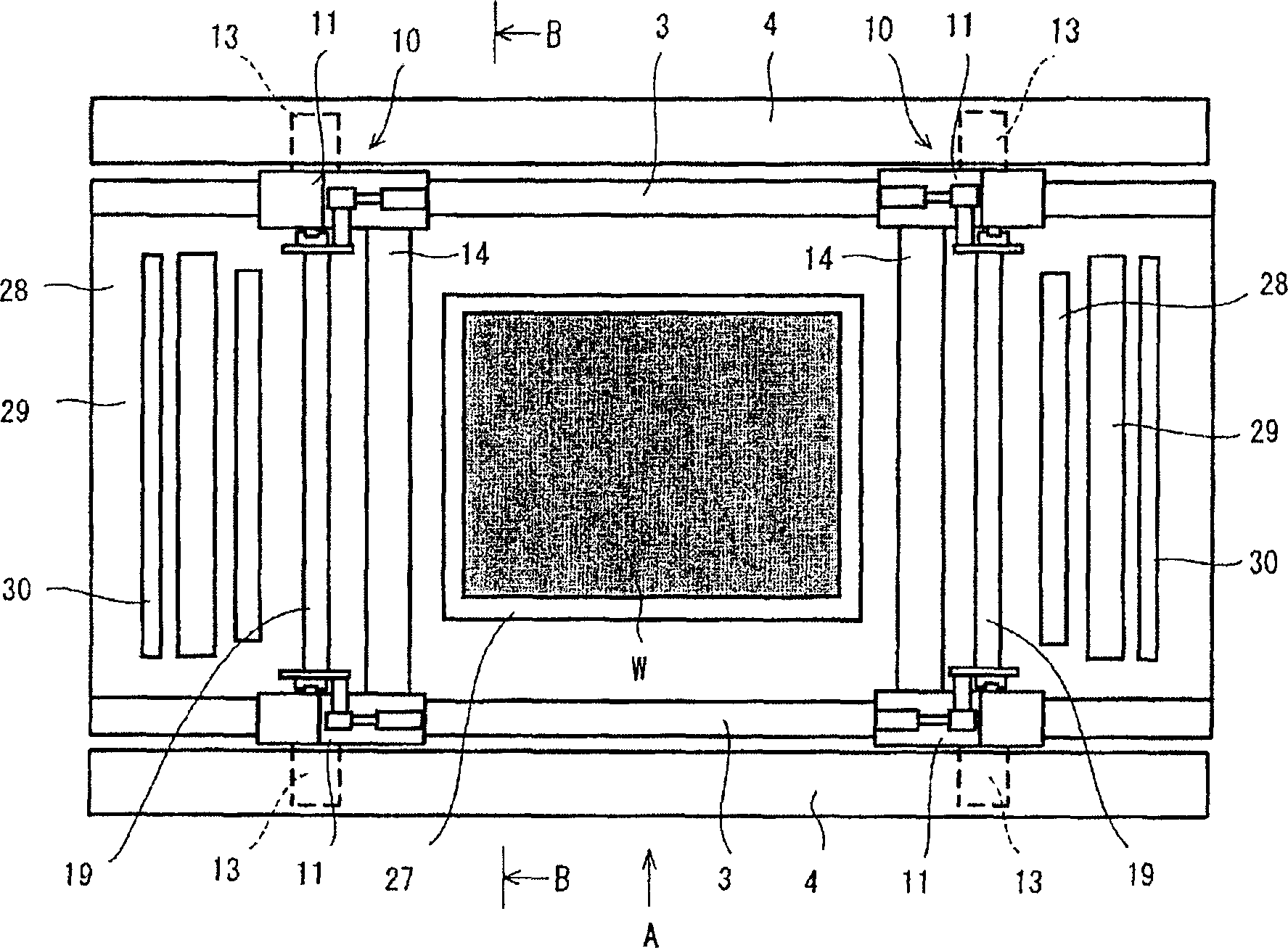
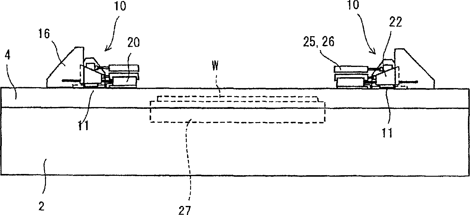
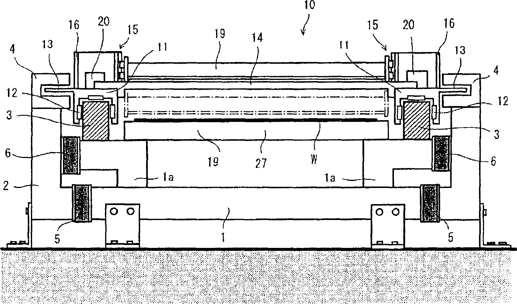
[0032] Embodiments of the present invention will be described below with reference to the drawings. figure 1 is an overall plan view of the coating device according to the present invention, figure 2 yes figure 1 A direction to the view, image 3 From figure 1 The enlarged view seen in the B-B direction, Figure 4 yes figure 2 The enlarged view of the main part, Figure 5 From Figure 4 A diagram of a moving body viewed from the opposite side.

[0033] The coating device is supported on the ground by a base frame. The base frame includes a first base frame and a second base frame. An L-shaped sub-frame 1a is provided on the upper portion of the first base frame 1, and a pair of rails 3 made of stone with a small coefficient of thermal expansion are provided horizontally and in parallel on the sub-frame 1a.

[0034] On the outside of the pair of rails 3 , a linear motor support portion 4 is arranged in parallel with the guide rails 3 as viewed from the front view. T...


PUM


Abstract

Provided is a coating device in which a synchronous deviation of the movement of a lateral traveling body does not appear as distortion of a slit nozzle. If a screw flight 23 is rotated by driving a motor 20, a wedge nut member 22 moves along a guide rail 21, owing to the movement of this wedge nut member 22, a wedge cam 24 abutting on the inclined plane of the wedge nut member 22 and an elevator 18 move along a guide rail 17 in a vertical direction, and the slit nozzle 19 rises and falls.

Description

technical field [0001] The present invention relates to a coating device for coating a coating liquid on a substrate surface such as a glass substrate. Background technique [0002] Patent Document 1 proposes a coating device for forming color filters of three primary colors on a glass substrate for color liquid crystals, and a device for coating phosphor pastes of three primary colors on a light emitting substrate for a plasma display. [0003] In the coating apparatus disclosed in Patent Document 1, two slit nozzles are arranged above a stage moved by a ball screw, two glass substrates are placed on the stage above the stage, and The two slit nozzles described above are used to coat two glass substrates at the same time, so the time is shortened compared to coating with one slit nozzle. [0004] In the coating device disclosed in Patent Document 2, a substrate mounting table is arranged between a pair of rails, and three gate-type moving mechanisms are arranged across the...

Claims


Application Information

Patent Timeline
IPC IPC(8): B05C5/02B05B13/04
CPCB43K3/04B43K23/12B43K24/02
Inventor 山口和伸楫间淳生
Owner 艾美柯技术株式会社
Why Eureka
Try Eureka