Video coding/decoding method and apparatus

一种视频编码、视频解码的技术,应用在视频解码领域,能够解决编码位数量增加等问题

Inactive Publication Date: 2006-09-13
KK TOSHIBA
View PDF1 Cites 28 Cited by
  • Summary
  • Abstract
  • Description
  • Claims
  • Application Information

AI Technical Summary

Problems solved by technology

Therefore, there is a problem in that two motion vectors respectively corresponding to the forward and backward images must be motion compensated for each unit area (for example, a macroblock or a cell obtained by dividing the macroblock), so Requires coding bits for many motion vectors compared to forward prediction with a single motion vector
Another problem is that when performing motion-compensated prediction from multiple forward and backward frames, motion vectors corresponding to these reference frames are required, resulting in an increase in the number of coded bits for these motion vectors
For this reason, when encoding these motion vectors, a problem arises in that the number of encoded bits of these motion vectors increases

Method used


Image

  • Video coding/decoding method and apparatus
  • Video coding/decoding method and apparatus
  • Video coding/decoding method and apparatus

Examples


Embodiment Construction

[0025] Embodiments of the present invention will be described below with reference to these drawings.

[0026] (coding)

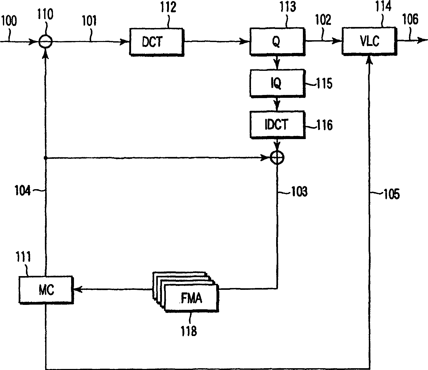
[0027] exist figure 1 The video encoding device shown in can be realized by hardware, and can be realized by a computer by employing software. Some processes can be performed in hardware, and the remainder can be performed in software.

[0028] exist figure 1 In this method, the input image signal 100 is input to the subtractor in units of frames (or images) to generate a prediction error signal 101 , which is an error of the predicted image signal 104 relative to the input video signal 100 . The predicted image signal 104 is generated from at least one reference frame image signal (or reference image signal) temporarily stored in a reference frame memory bank (FMA) 118 by a motion compensated prediction unit (MC) 111 . The reference frame memory bank 118 includes a plurality of frame memories.

[0029] The motion compensation prediction unit 111 perfo...


PUM


Abstract

A video encoding method comprises storing a plurality of encoded frames (rf0, rf1, rf2) of a video in a memory, generating a to-be-encoded frame (current) which is divided in a plurality of regions (A to E) including at least one encoded region (A to D) and at least one to-be-encoded region (E), generating a predictive vector (MV) of the to-be-encoded region of the to-be-encoded frame using a plurality of motion vectors (RCMV) as a plurality of reference vectors, the motion vectors being generated with respect to at least one reference frame selected from the encoded frames for a motion compensative prediction when encoding an original region of the encoded region around the to-be-encoded region of the to-be-encoded frame, and encoding the to-be-encoded frame to generate encoded video data.

Description

[0001] This application is a divisional application of Chinese Patent Application No. 03143053.8 filed on June 17, 2003, entitled "Video Encoding / Decoding Method and Device". technical field [0002] The present invention relates to a video coding method for compressing and coding a video signal and a video coding device thereof, and a video decoding method for decoding compressed and coded data to restore it to an original video signal. Background technique [0003] The compression and decoding systems for video images that are widely put into practical use include MPEG-1 (ISO / IEC11172-2), MPEG-2 (ISO / IEC 13818-2), MPEG-4 (ISO / IEC 14496 -2) and ITU-TH.263. In these coding systems, motion compensation predictive coding is accomplished by a combination of intra-coded pictures (I pictures), forward predictive intra-coded pictures (P pictures), and bidirectional predictive coded pictures (B pictures). The P picture is decoded using the P picture or I picture just before that a...

Claims


Application Information

Patent Timeline
Patent Type & Authority Applications(China)
IPC IPC(8): H04N7/26H04N7/32H04N19/105G06T9/00H03M7/36H04N7/24H04N19/134H04N19/137H04N19/139H04N19/167H04N19/172H04N19/174H04N19/176H04N19/189H04N19/196H04N19/423H04N19/46H04N19/463H04N19/50H04N19/503H04N19/51H04N19/513H04N19/577H04N19/61H04N19/625H04N19/70H04N19/91
CPCH04N19/00781H04N7/366H04N19/00587H04N7/50H04N7/26851H04N19/00672H04N7/26872H04N7/26765H04N19/00715H04N19/00696H04N19/51H04N19/52H04N19/567H04N19/573H04N19/61
Inventor 菊池義浩中條健古藤晋一郎
Owner KK TOSHIBA
Why Eureka
Try Eureka