Showerhead engine assembly

A technology for shower heads and appliances, applied in showers, bathtubs, jet devices, etc., can solve the problems of expensive manufacturing, blocked outlet holes, etc., and achieve the effect of reducing spare parts, reducing the number of parts, and shortening assembly time

Inactive Publication Date: 2006-09-27
ALSONS CORP
View PDF0 Cites 13 Cited by
  • Summary
  • Abstract
  • Description
  • Claims
  • Application Information

AI Technical Summary

Problems solved by technology

[0008] These systems have complex internal parts that must be sealed against each other, are relatively expensive to manufacture, and, due to the complexity of their parts, often do not operate in a completely leak-tight manner during use
In addition, the outlet holes of shower heads are often clogged with impurities, resulting in an almost random spray pattern

Method used


Image

  • Showerhead engine assembly
  • Showerhead engine assembly
  • Showerhead engine assembly

Examples


Embodiment Construction

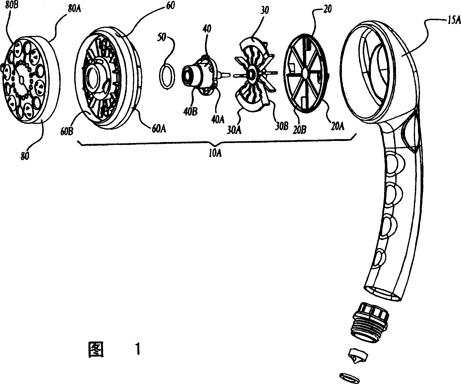
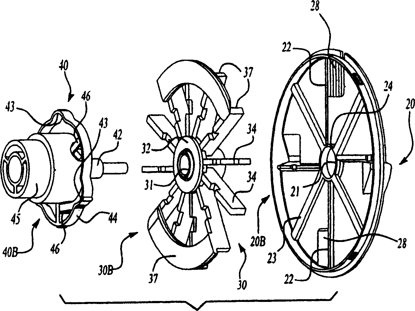
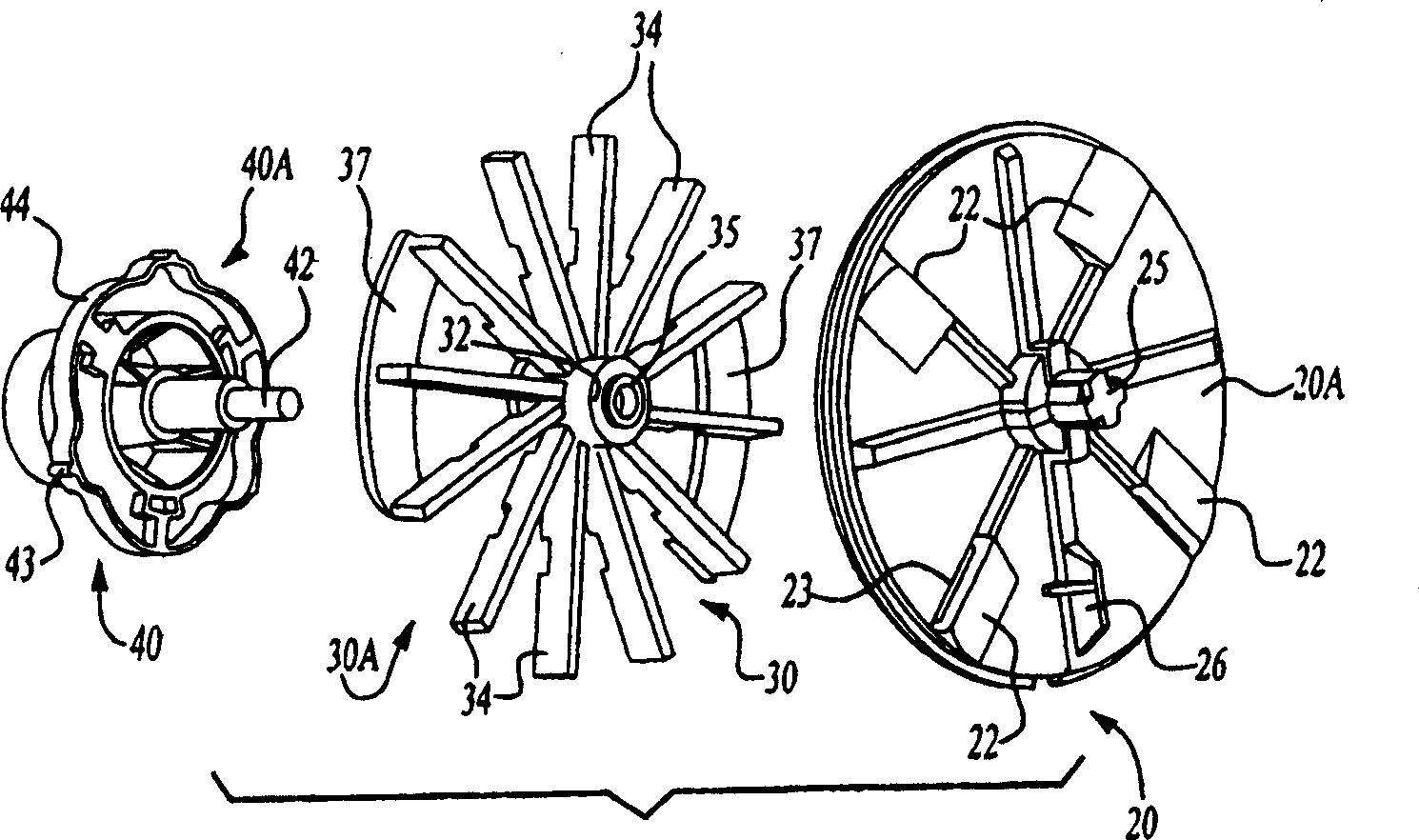
[0037] Referring first to the drawings, FIG. 1 discloses an assembled view of a preferred embodiment of a hand-held embodiment of a showerhead appliance assembly 10A of the present invention. Figures 7a, 7b, 8a, 8b and 8c give additional views of the hand showerhead housing and shroud 15A. The shower head appliance assembly 10 of the present invention includes a stationary part 20 , a rotating part 30 , an engaging part 40 , a sealing ring 50 , a pressure plate 60 and a panel 80 .

[0038] High pressure water at about 137895.2 to 551580.8 Pa (20 to 80psi (lb / in 2 ) into the rear end of the shower head housing of the present invention, 551580.8 Pa (80 lbs / in 2 ) with a maximum flow rate of 9.4625 L / min (2.5 GPM). Water is pushed through the stationary member 20 into the rotating member 30 , into and through the pressure plate 60 , and exits through the panel 80 . The rotating member 30 , the sealing ring 50 and the engaging member 40 are inserted into the pressure plate 60 ....


PUM


Abstract

The invention relates to a shower ejector, which can supply continuous, deflected, and aerated frog, wherein said invention comprises: static element, rotational element, connector, pressure plate, panel and sealing ring; the pressure plate and the panel are arranged with holes through with liquid; the deflected surface of panel can realize the change between different water flow types; opposite to the static element, the rotator rotates or stops rotation; said static element comprises a couple of stop edges connected and detached with a rotator; when the rotator is detached and rotates freely, the water will pass the channel of rotator to rotate the rotator, to generate vortex and impulse frog.

Description

[0001] related application [0002] This application claims priority to U.S. Provisional Application No. 60 / 128,289, filed April 8, 1999, and filed April 10, 2004, by Alsens LLC, application number 00106472 .X and the title of the invention is a divisional application for a shower head appliance assembly. technical field [0003] The present invention relates to showerhead fixture assemblies and water aerators, and more particularly to showerhead fixture assemblies having different combinations of continuous and pulsed sprays. Background technique [0004] Many shower head assemblies which operate in multiple functional modes are known in the art. These components provide a fixed spray pattern combined with a massaging action due to either pulsing or swirling of the water through the shower head. Various systems include: [0005] (1) The selection disc installed in the selector housing in a detachable and rotatable manner. The selector disc has an inlet end facing the in...

Claims


Application Information

Patent Timeline
Patent Type & Authority Applications(China)
IPC IPC(8): B05B1/16B05B15/02A47K3/28B05B1/18B05B3/04B05B15/06B05B15/522
CPCB05B3/049B05B3/04B05B15/0233B05B1/1645B05B15/061B05B1/185B05B15/5225
Inventor I·格林伯格M·莱夫A·格诺萨J·E·佩特罗维克
Owner ALSONS CORP
Why Eureka
Try Eureka