Detent escapement for timepieces

An escapement, astronomical technology, used in escapements, clocks, mechanically driven clocks, etc., can solve problems such as edge collision and breakage

Inactive Publication Date: 2006-10-04
MONTRES BREGUET
View PDF1 Cites 8 Cited by
  • Summary
  • Abstract
  • Description
  • Claims
  • Application Information

AI Technical Summary

Problems solved by technology

Furthermore, the fingers are formed by edges which can bump and break off in the mechanism if the mechanism is not adjusted correctly

Method used


Image

  • Detent escapement for timepieces
  • Detent escapement for timepieces
  • Detent escapement for timepieces

Examples


Embodiment Construction

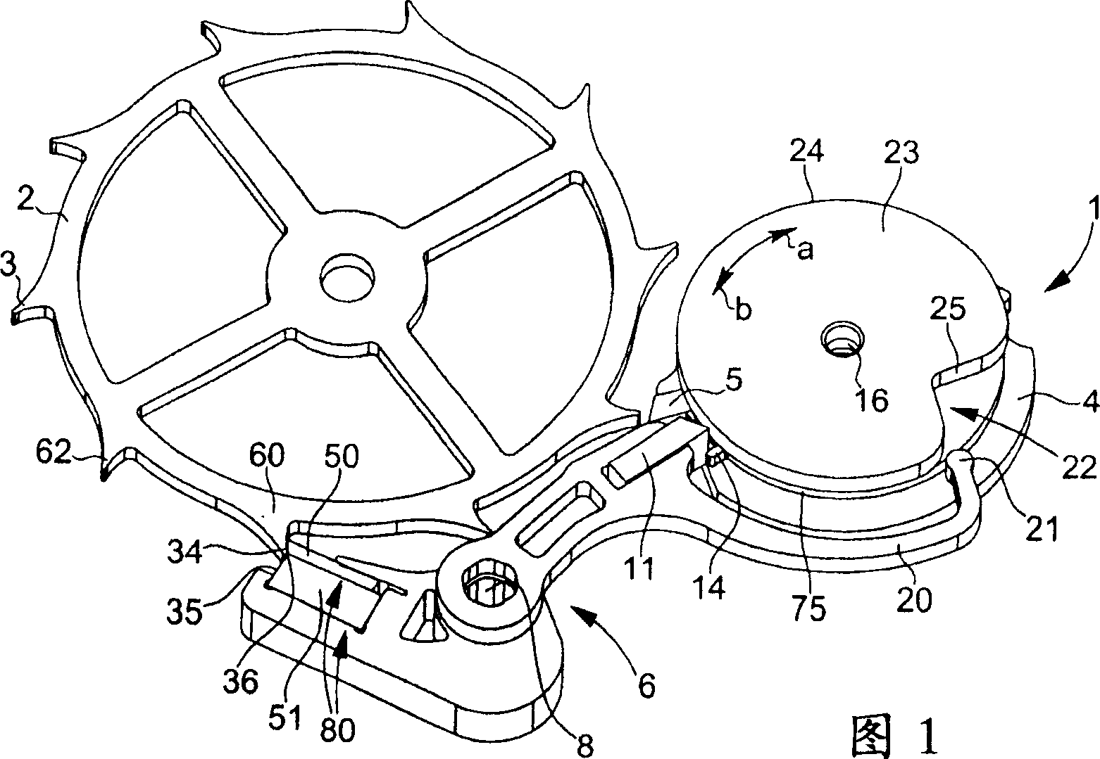
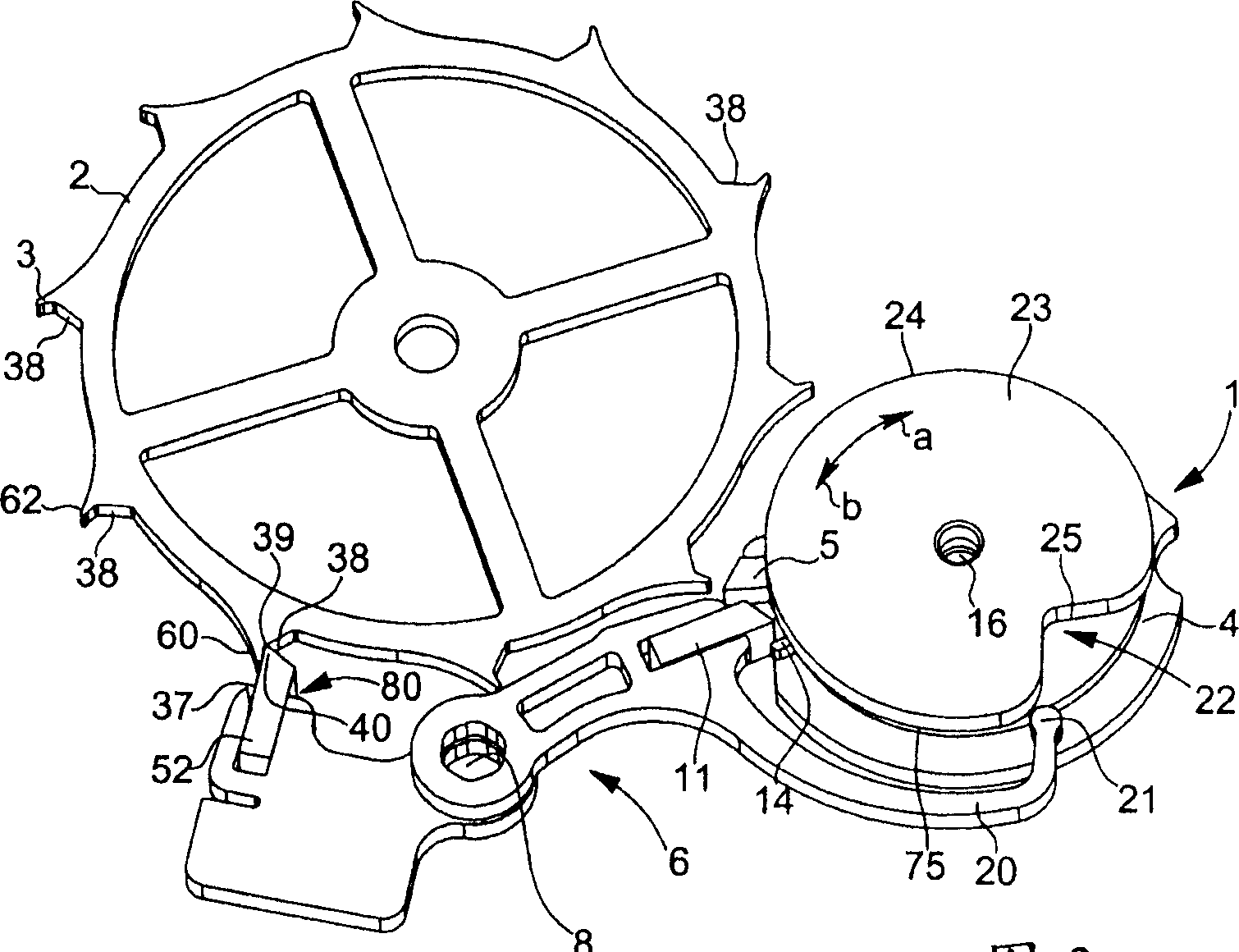
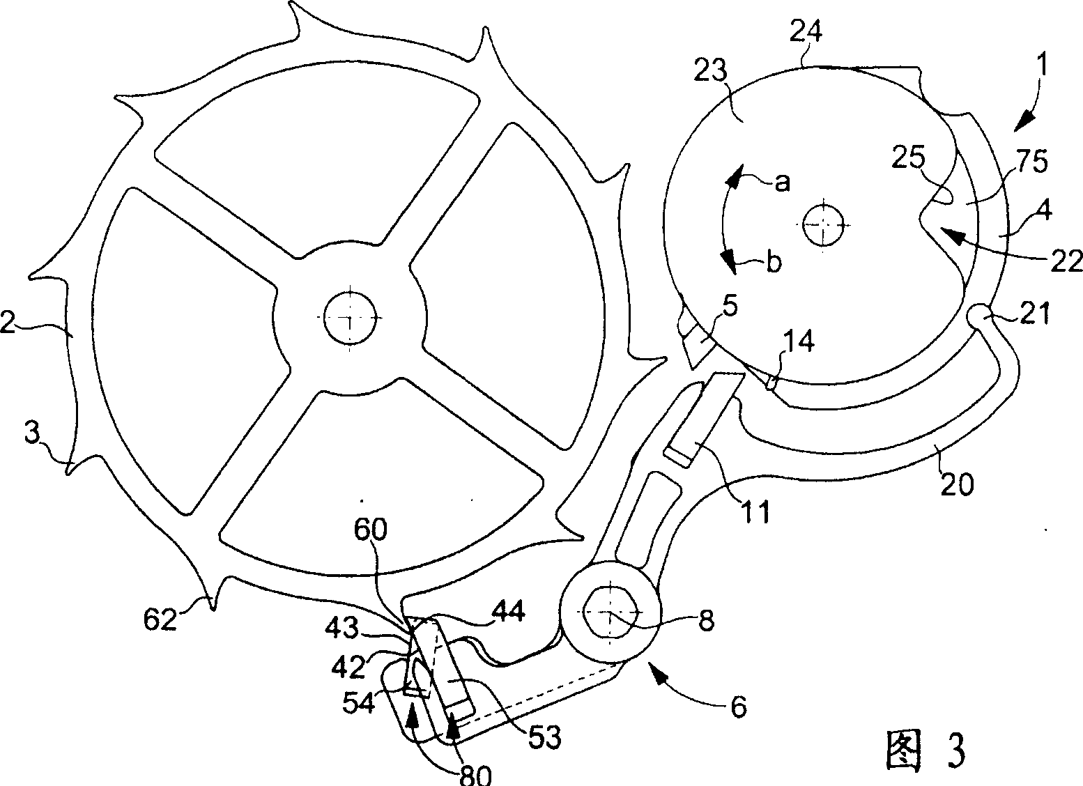
[0016] The accompanying drawings show the detent escapement forming the subject of the invention. The detent escapement comprises an escape wheel 2 with teeth 3 . Although not shown, the escape wheel 2 is driven by a transmission train of a timepiece that receives driving force from a barrel. Disc 1 is mounted on a balance shaft 16 not shown in the figure. The disk 1 comprises a large disk 4 on which an impact shoe 5 is mounted and a small disk 23 with a circular periphery 24 in which a notch 22 with a rising edge 25 is formed. The first actuating claw 14 is installed on the big disk 4 tops. The figures show that the finger 14 protrudes from a disc 75 sandwiched between the discs 4 and 23 . The escapement also includes a locking member 6 in the form of a rod hinged on a pin 8 . The lock 6 comprises a first part and a second part fixedly connected by a pin 8 . The figures show that the first part comprises a locking device 80 cooperating with the teeth 3 of the escape whee...


PUM


Abstract

The escapement includes a large roller 4 carrying an impulse pallet stone 5 surmounted by a first finger-piece 14 and a small roller 23 in which a notch 22 is made. A blocking member carries, on the one hand, means 80 for locking the escape wheel 2, and on the other hand, a second finger-piece 11 arranged for cooperating with the first finger-piece 14, said blocking member also including a follower 20 ending in a beak 21, said beak acting on the small roller and particularly with notch 22 which is made therein. The first and second finger-pieces 14 and 11 are respectively rigidly secured to the table roller and the blocking member.

Description

technical field [0001] The invention relates to a detent escapement for a timepiece, comprising an escape wheel with teeth, a balance wheel on which a disc is fixed on its balance shaft, and a lock in the form of a lever hinged on a pin The stopper, wherein the disc includes a large disc with an impact fork and a first actuating claw installed on the upper part and a small disc with a notch formed in the outer circumference of the circle, the locking part has There are means for locking the escape wheel, a second actuating dog and a follower ending in a beak arranged to cooperate with the rising edge of the notch of the small disc. Background technique [0002] A detent escapement conforming to the above description has been proposed in European Patent Application No. 03027929.3, filed 4 December 2003. However, in this patent application an elastic member acts on one of the actuating fingers - in this example the first finger forming part of the balance disc - so that when ...

Claims


Application Information

Patent Timeline
Patent Type & Authority Applications(China)
IPC IPC(8): G04B15/00G04B15/12G04B15/14
CPCG04B15/06
Inventor T·科奴斯A·卡贝萨斯朱林
Owner MONTRES BREGUET
Why Eureka
Try Eureka