
On-channel repeating apparatus and method for terrestrial digital television broadcasting service

A technology of digital TV broadcasting and co-channel, which is applied in broadcasting information relay, parts of color TV, parts of TV system, etc., can solve problems such as limitation of output feedback signal of co-channel relay station

Inactive Publication Date: 2006-10-18
ELECTRONICS & TELECOMM RES INST
View PDF0 Cites 5 Cited by
  • Summary
  • Abstract
  • Description
  • Claims
  • Application Information

AI Technical Summary

Problems solved by technology

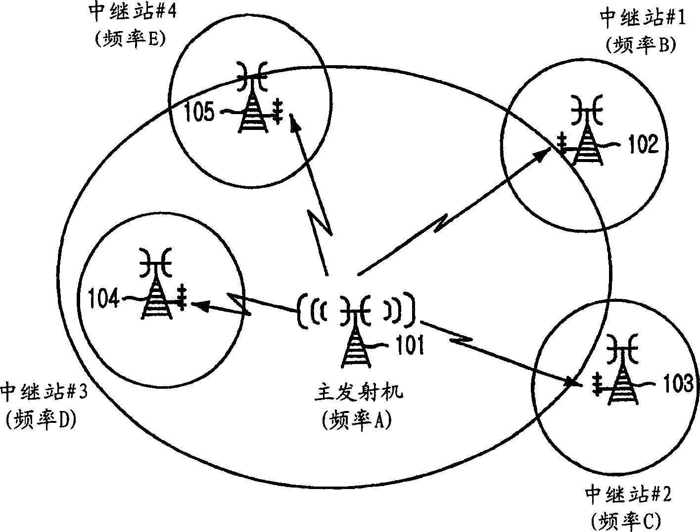
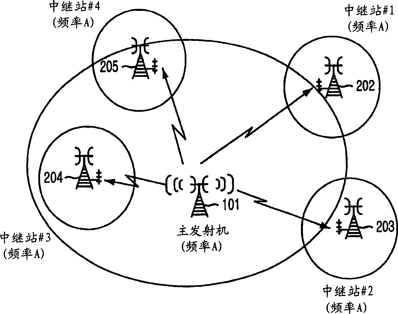
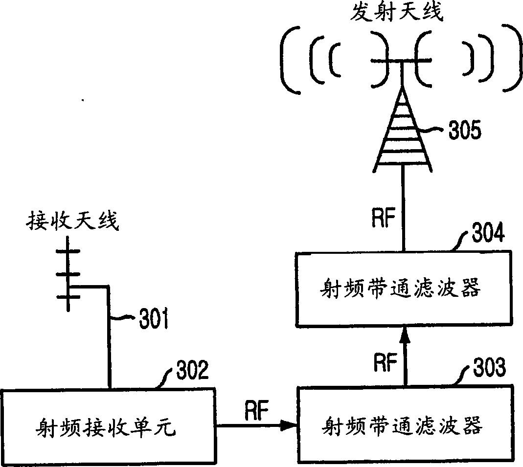
[0018] However, the conventional co-channel repeater mentioned above as shown in Figures 3 to 6 has some disadvantages: the transmission output of the co-channel repeater is limited due to the feedback signal caused by the low isolation of the transmit / receive antenna
[0019] Moreover, in the conventional co-channel relay stations of FIGS. 3 to 5, the characteristics of the output signal of the co-channel relay station are inferior to those of the input signal of the co-channel relay station because the transmission channel between the main transmitter and the co-channel relay station generates Noise and multipath signals, feedback signals due to low insulation of transmit / receive antennas, and system noise added from co-channel relay systems, etc. cannot be removed

Method used


Image

  • On-channel repeating apparatus and method for terrestrial digital television broadcasting service
  • On-channel repeating apparatus and method for terrestrial digital television broadcasting service
  • On-channel repeating apparatus and method for terrestrial digital television broadcasting service

Examples


Embodiment Construction

[0036] Figure 8 is an exemplary view illustrating the structure of a co-channel relay station according to a preferred embodiment of the present invention.

[0037] see Figure 8 , the co-channel relay station includes an RF receiving unit 802, an IF downlink converting unit 803, a demodulating unit 804, an equalizing unit 805, a modulating unit 806, an RF uplink converting unit 807, a high-power amplifying unit 808, a transmitting antenna 809 and a local Oscillator (LO) 810 .

[0038] Each element of the co-channel repeater station is briefly explained below.

[0039] The RF receiving unit 802 receives an RF (Radio Frequency) broadcast signal from a main transmitter through the receiving antenna 801 .

[0040] The frequency downlink conversion unit 803 converts the received RF broadcast signal into an IF (Intermediate Frequency) signal on the basis of the first reference frequency.

[0041] The demodulation unit 804 converts the converted IF signal into a baseband signal...


PUM


Abstract

A relay station and method for ATSC terrestrial digital television broadcasting services are disclosed. The co-channel relay station includes: a receiving unit for receiving radio frequency (RF) broadcast signals from the main transmitter; a frequency downlink conversion unit for converting received RF broadcast signals into intermediate frequency (IF) signals; a demodulation unit , used to convert the converted intermediate frequency signal into a baseband signal; an equalization unit, used to remove noise and multipath signals generated from the converted baseband signal; a modulation unit, used to convert the baseband signal into an intermediate frequency signal; frequency uplink The channel conversion unit is used to convert the intermediate frequency signal into a radio frequency broadcast signal; the high-power amplifying unit is used to amplify and relay the converted radio frequency broadcast signal; the transmitting unit is used to transmit the radio frequency broadcast signal output from the high-power amplifying unit and a signal synchronization unit that generates a first reference frequency, and generates a second reference frequency based on the first reference frequency so that the transmit / receive signal is frequency and phase synchronized.

Description

technical field [0001] The present invention relates to an on-channel repeater device and method in which Advanced Television Systems Committee ATSC terrestrial digital television broadcast signals are relayed on-channel, and, more particularly, to an ATSC terrestrial A co-channel repeater station and method for digital television broadcasting services, wherein: a radio frequency (hereinafter referred to as "RF") broadcast signal transmitted from a main transmitter is converted into a baseband signal by using a high-performance equalizer, and the converted Noise and multipath signals generated due to the transmission channel between the main transmitter and the co-channel relay station and feedback signals generated due to low insulation of the transmit / receive antenna of the co-channel relay station are removed from the baseband signal, and the converted baseband signal is again The conversion to the RF broadcast signal is such that the same output signal as the input signal ...

Claims


Application Information

Patent Timeline
Patent Type & Authority Applications(China)
IPC IPC(8): H04N7/015H04H20/00H04H20/06H04N5/21H04N5/40H04N5/44H04N5/455
CPCH04H20/06H04N5/211H04N5/40H04N5/455H04N21/426H04N21/6112H04N7/015
Inventor 朴成益李镕台金承源阴淏珉徐在贤李寿寅
Owner ELECTRONICS & TELECOMM RES INST
Learn More